
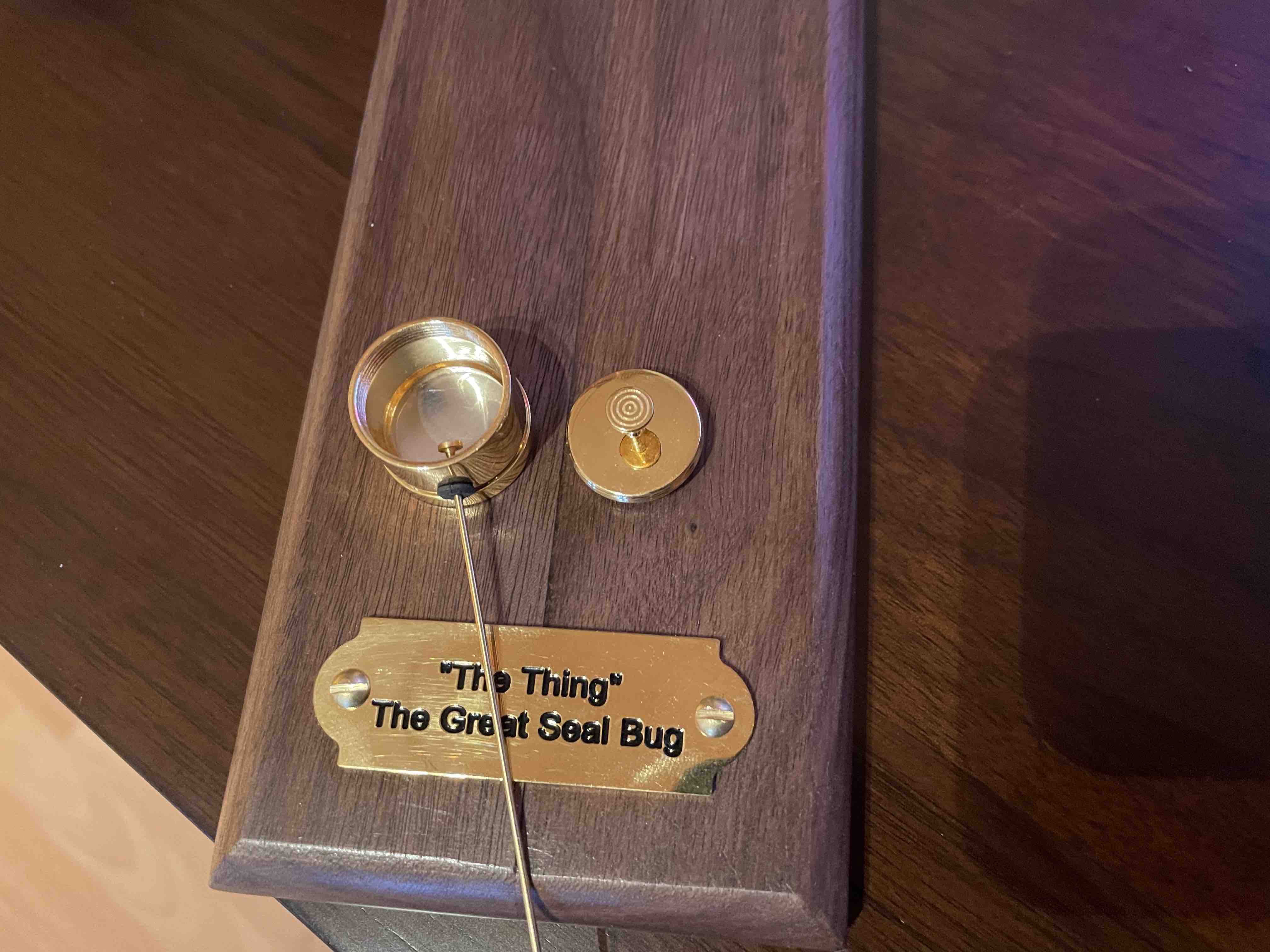
75 Years ago, something was found... it would become known as "The Thing" aka "The Great Seal Bug".
This website isn't for re-telling the story, it's well documented on Wikipedia.
This website is dedicated to creating a model of it and the process I went through in order to create an accurate representation from the few images of it available on the internet.
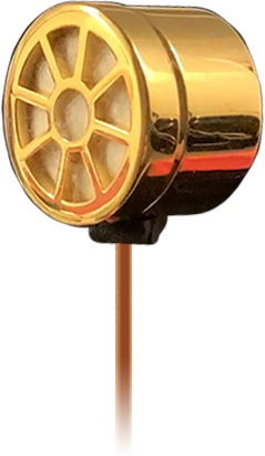
The Thing was originally mounted inside The Great Seal, however, I wanted my version to be touched, taken down, disassembled when the curious ask about it, and then quickly mounted back on the wall.
So my version is mounted to a plinth, which has an embedded magnet. The Thing also has an embedded magnet so it securely snaps into place

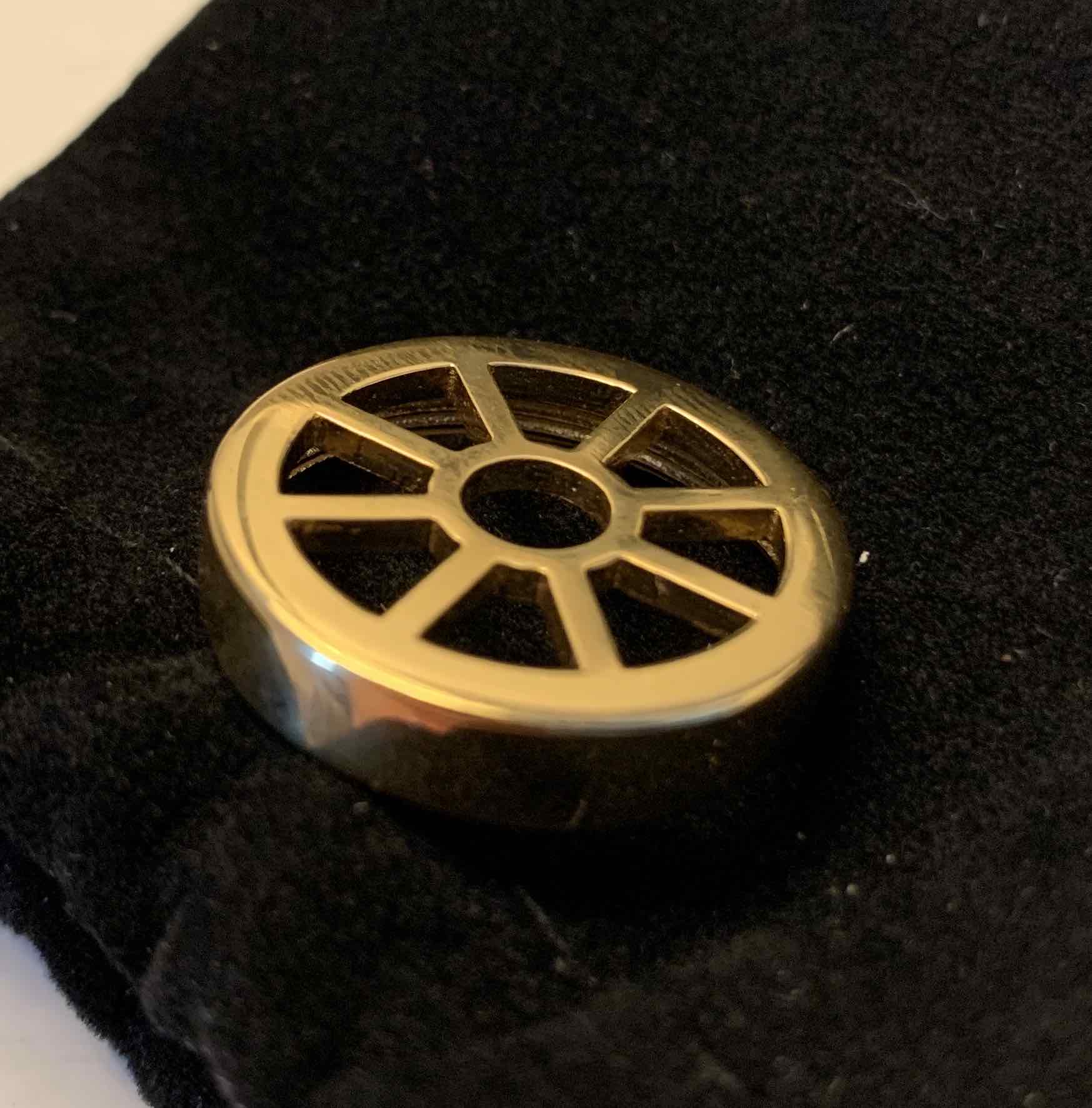
 The final piece
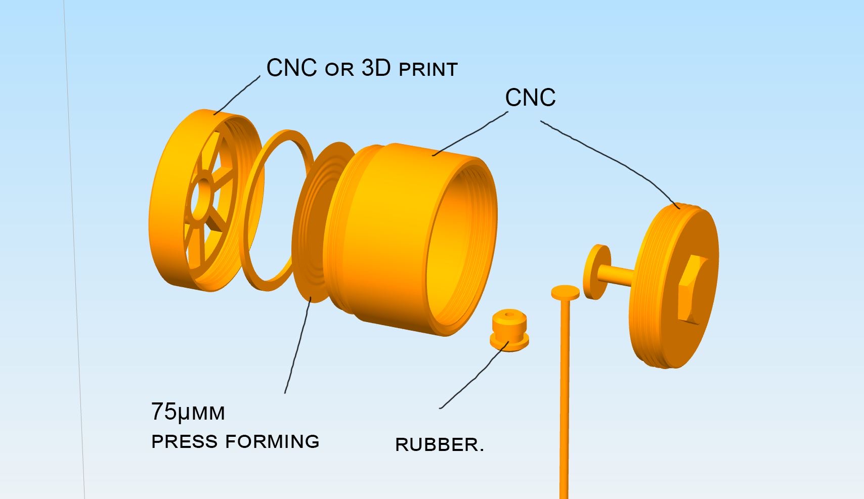
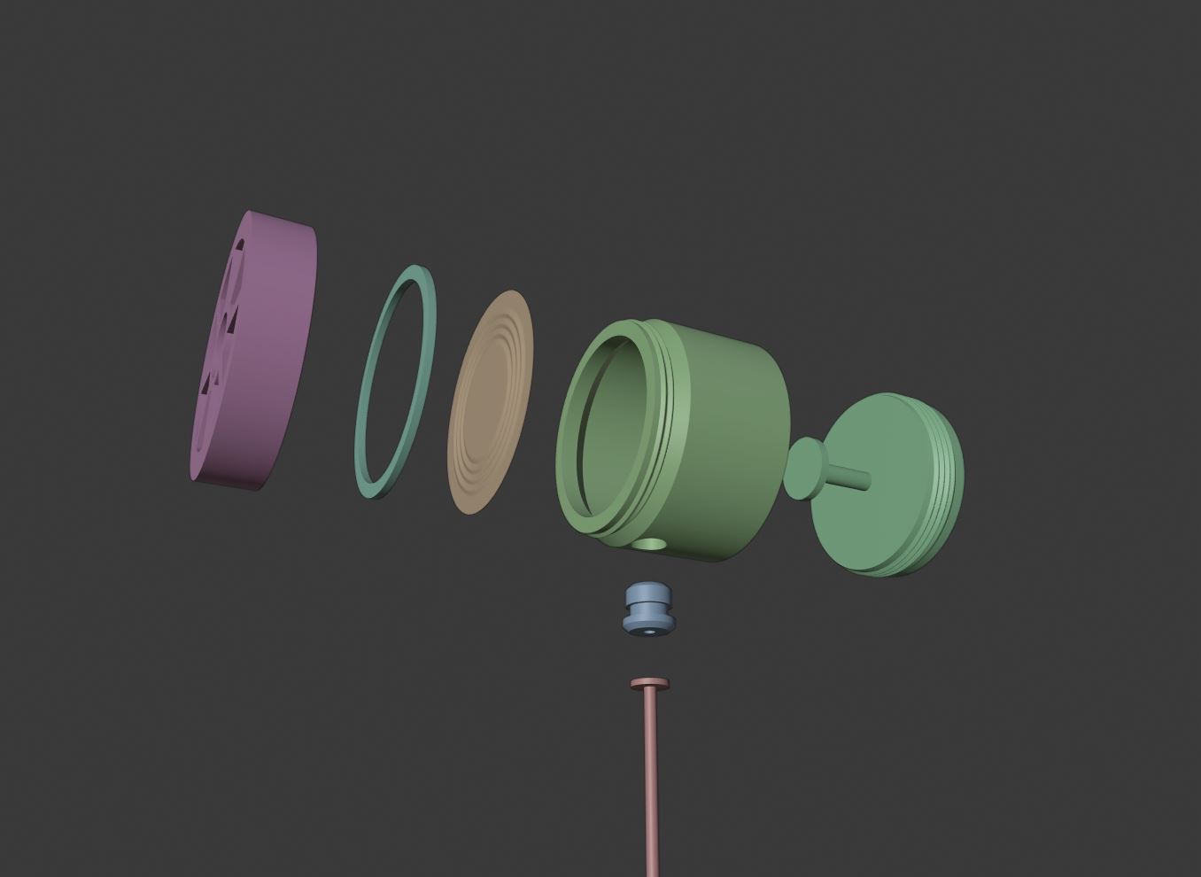 Part are modelled in Blender
 I got in contact with a few different CNC shops, unfortunately they weren't able to help.
I would love to have done this myself, I like the look of the Bantam Tools CNC
but it's out of my range for a small project. In the end I went with Shapeways for the main body
assembly.
I got in contact with a few different CNC shops, unfortunately they weren't able to help.
I would love to have done this myself, I like the look of the Bantam Tools CNC
but it's out of my range for a small project. In the end I went with Shapeways for the main body
assembly.
 1st Parts arrives from 3d printer, screw top
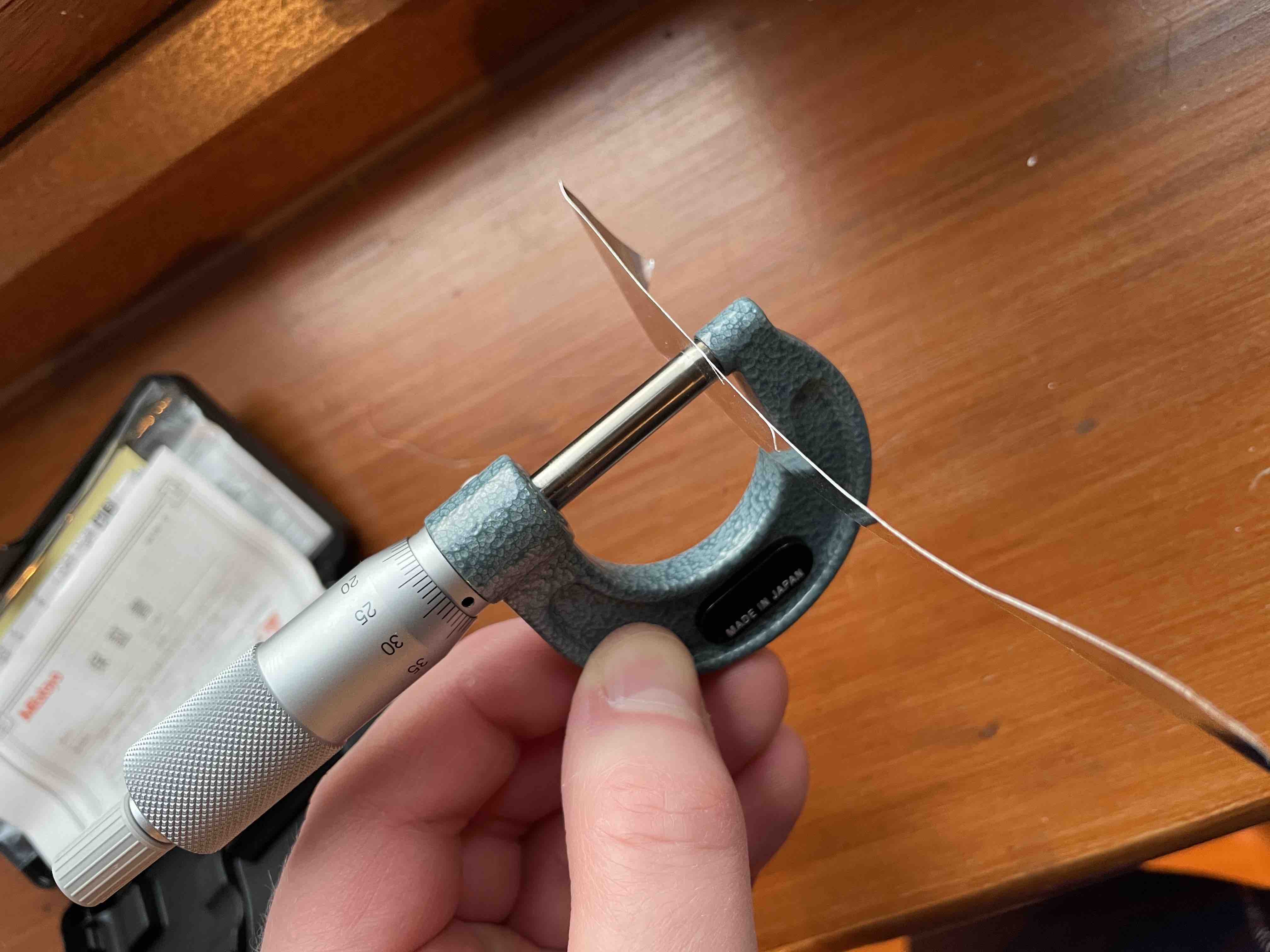
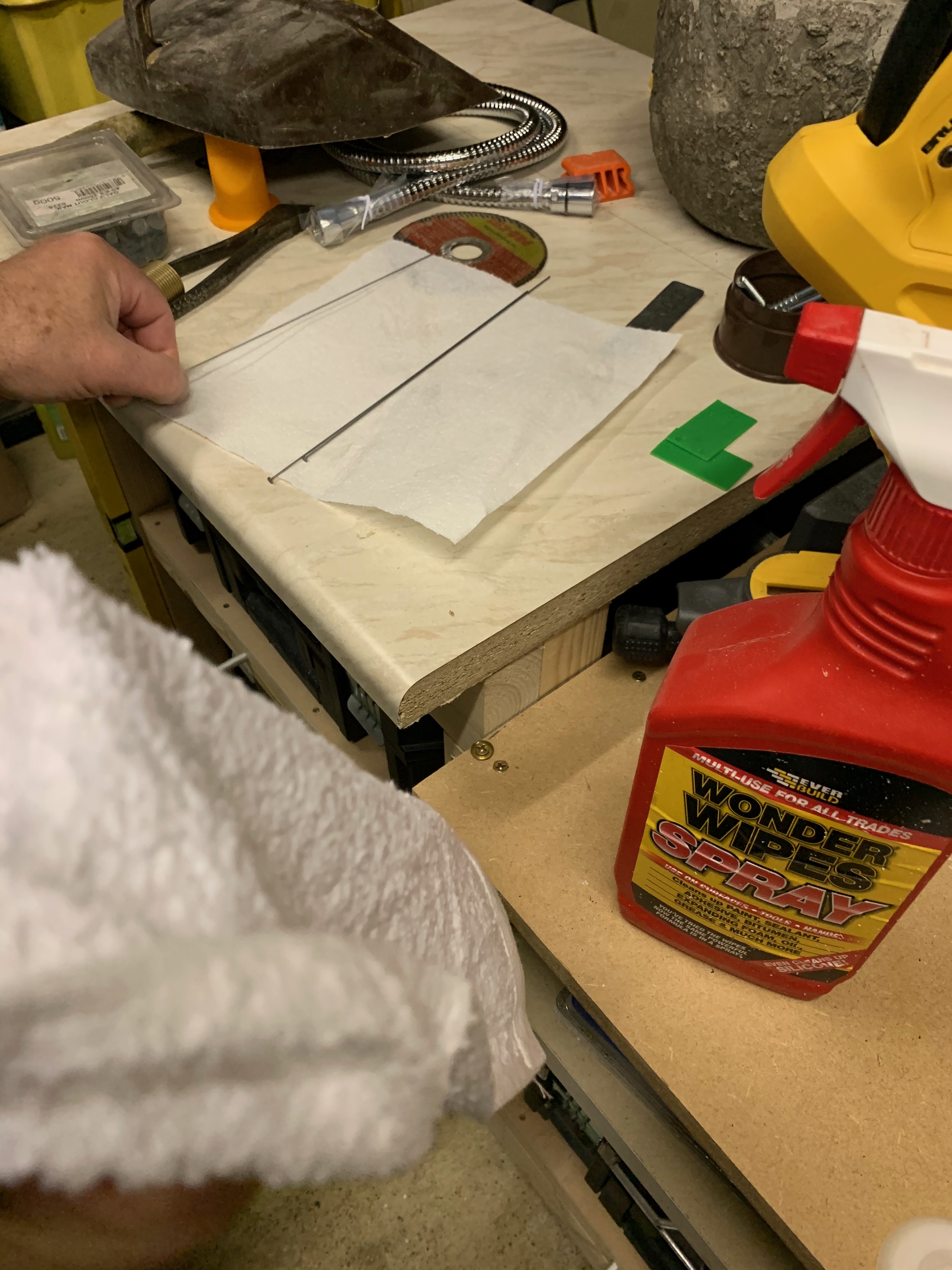
 The membrane is very thin, 75 microns, I have no idea where I can get a material that thin,
a coke cake is thicker than that, also I need something to measure it
The membrane is very thin, 75 microns, I have no idea where I can get a material that thin,
a coke cake is thicker than that, also I need something to measure it
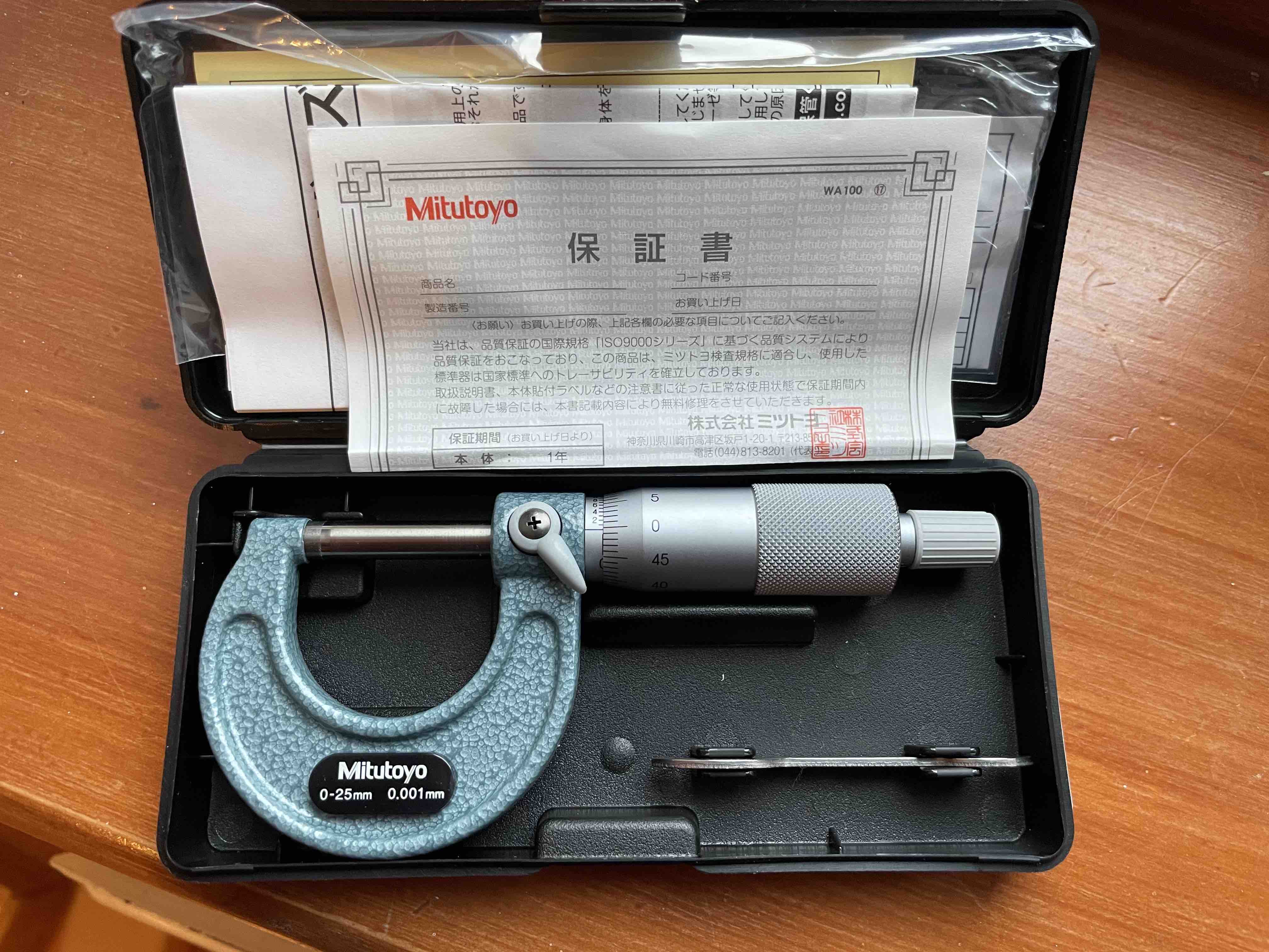 I buy an extremely accurate Japanese micrometer, this tool is so beautifully made
(Mitutoyo 103-129 Outside)
I buy an extremely accurate Japanese micrometer, this tool is so beautifully made
(Mitutoyo 103-129 Outside)
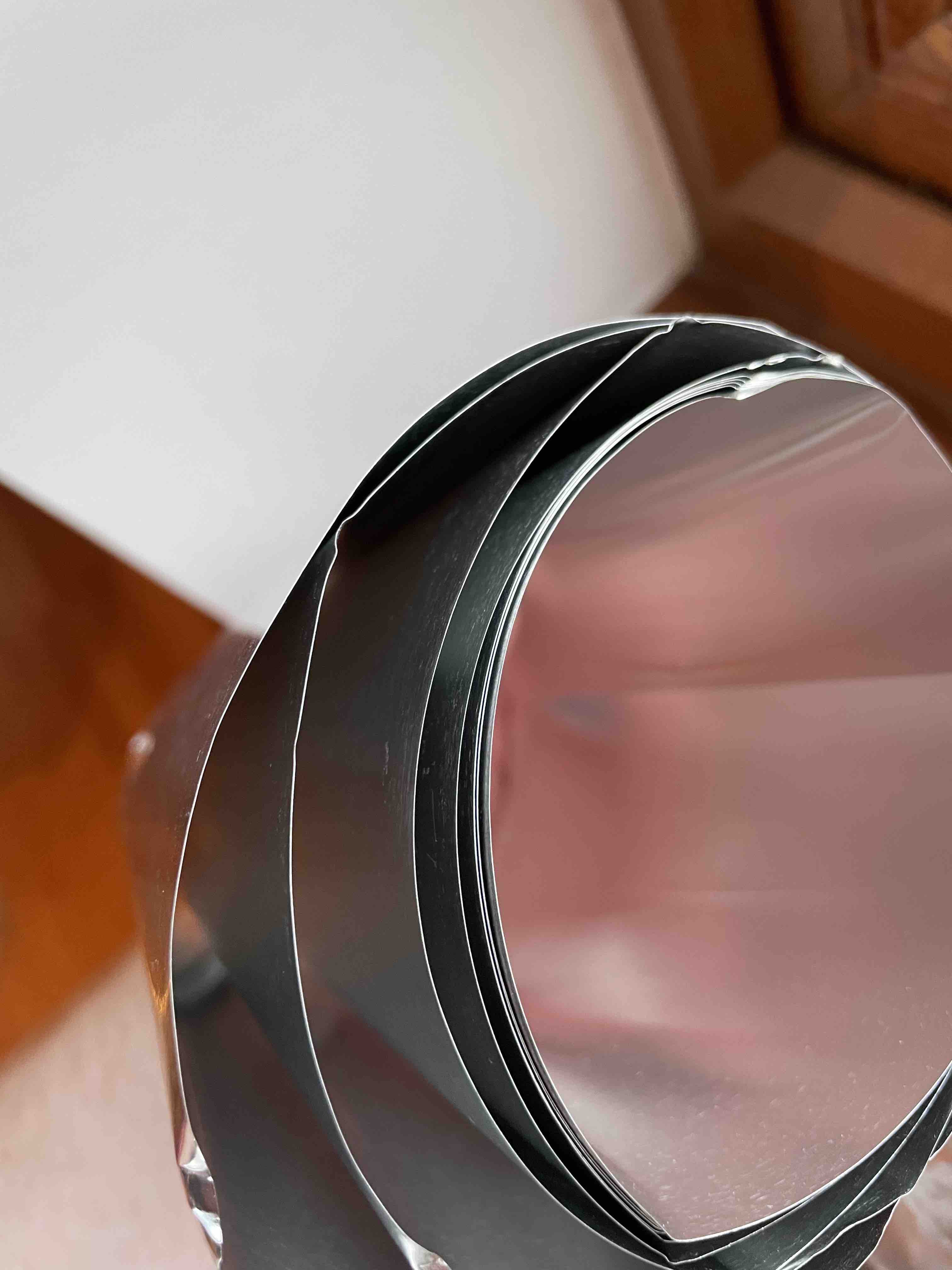
 I find a roll of material from Amazon, it's the perfect size (1100 Aluminum Shim Stock, Full Hard Temper, AISI 1100-H18, 0.003" Thick, 6" Width, 100" Length)
 Other parts arrive, o-ring and grommet were printed in metal just to see,
as at this point, I didn't know what I was going to do about the rubber grommet
or the seal
Other parts arrive, o-ring and grommet were printed in metal just to see,
as at this point, I didn't know what I was going to do about the rubber grommet
or the seal
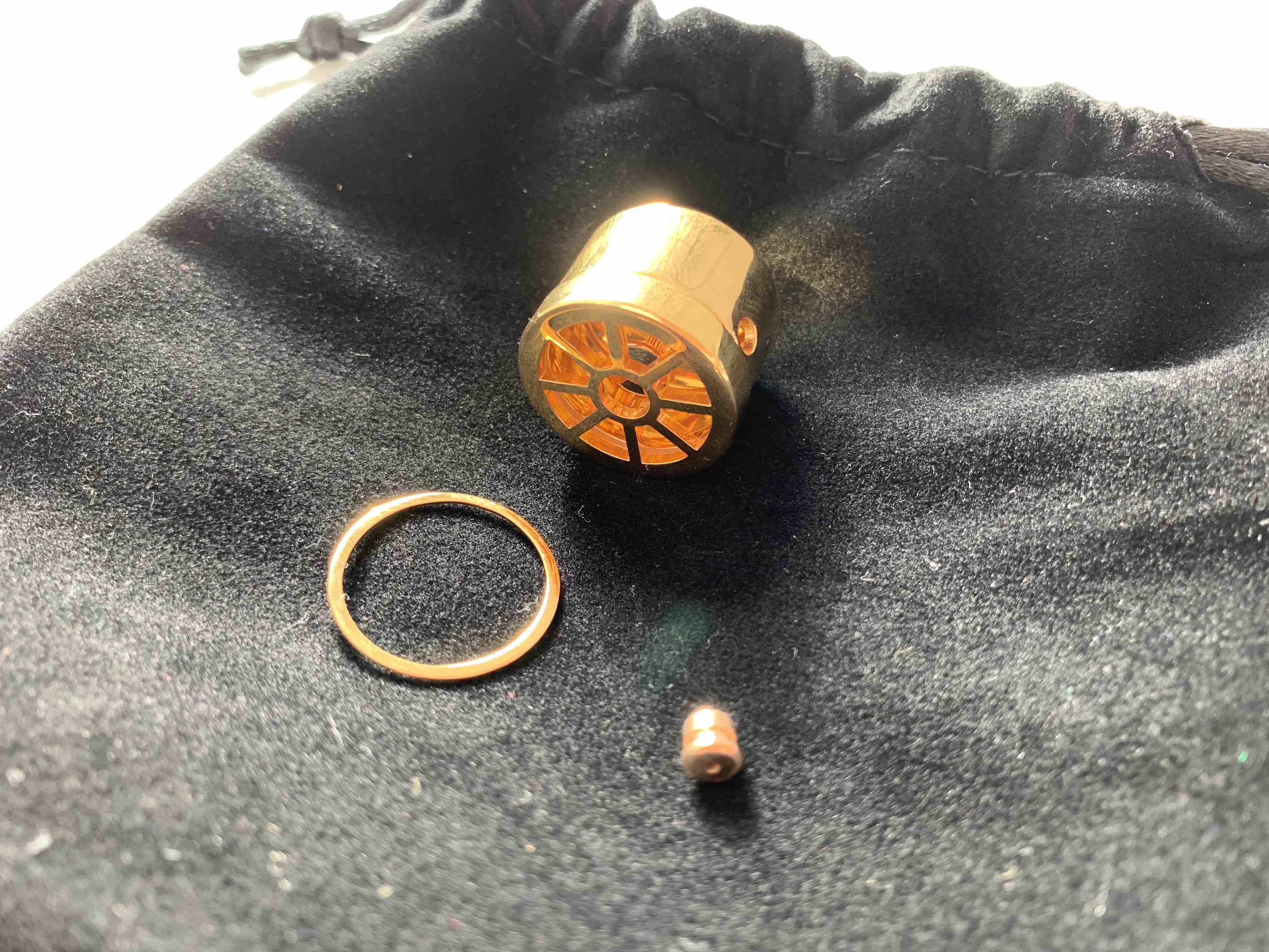
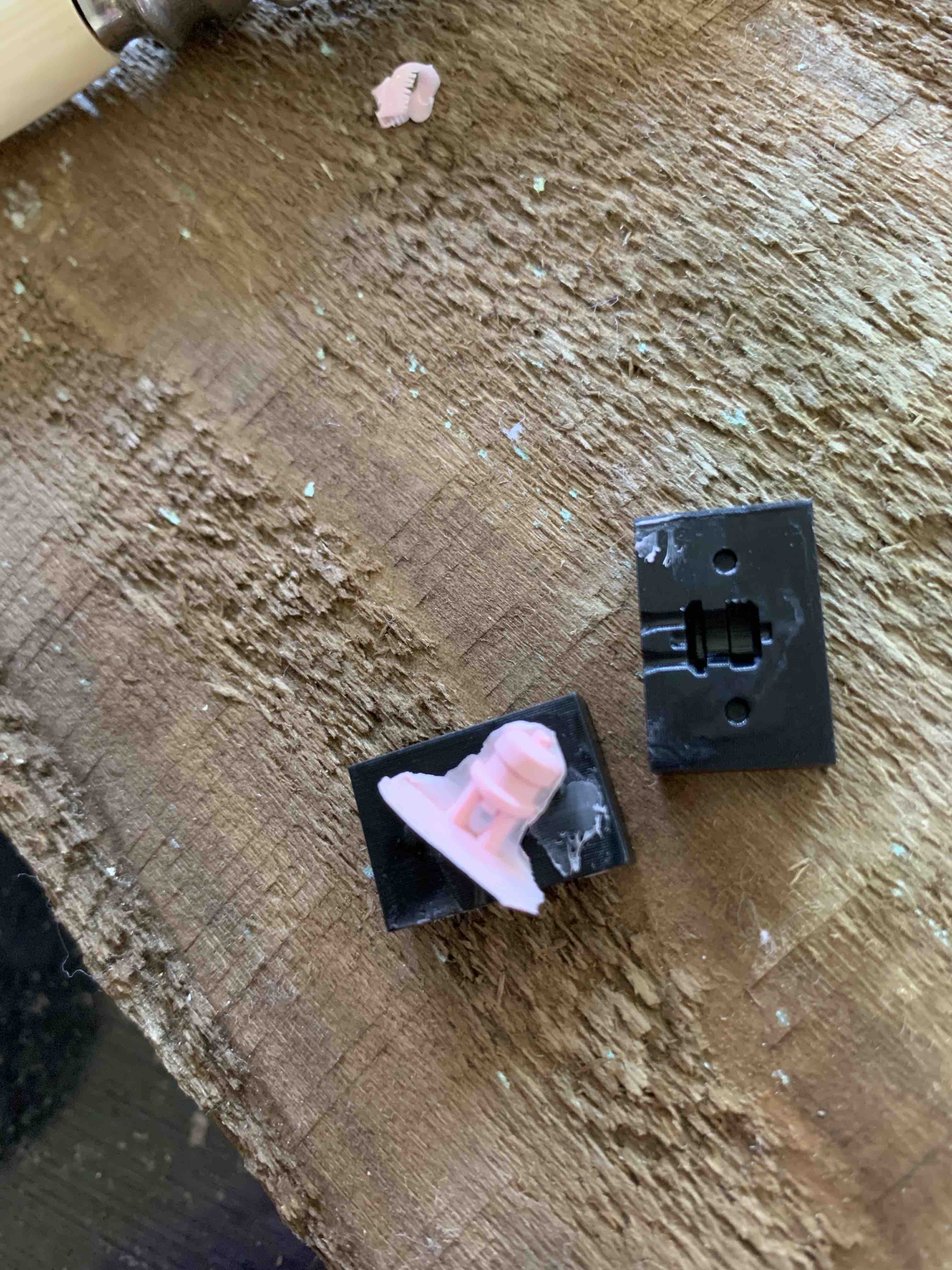
 All parts together, note the back screw plate and a plastic o-ring
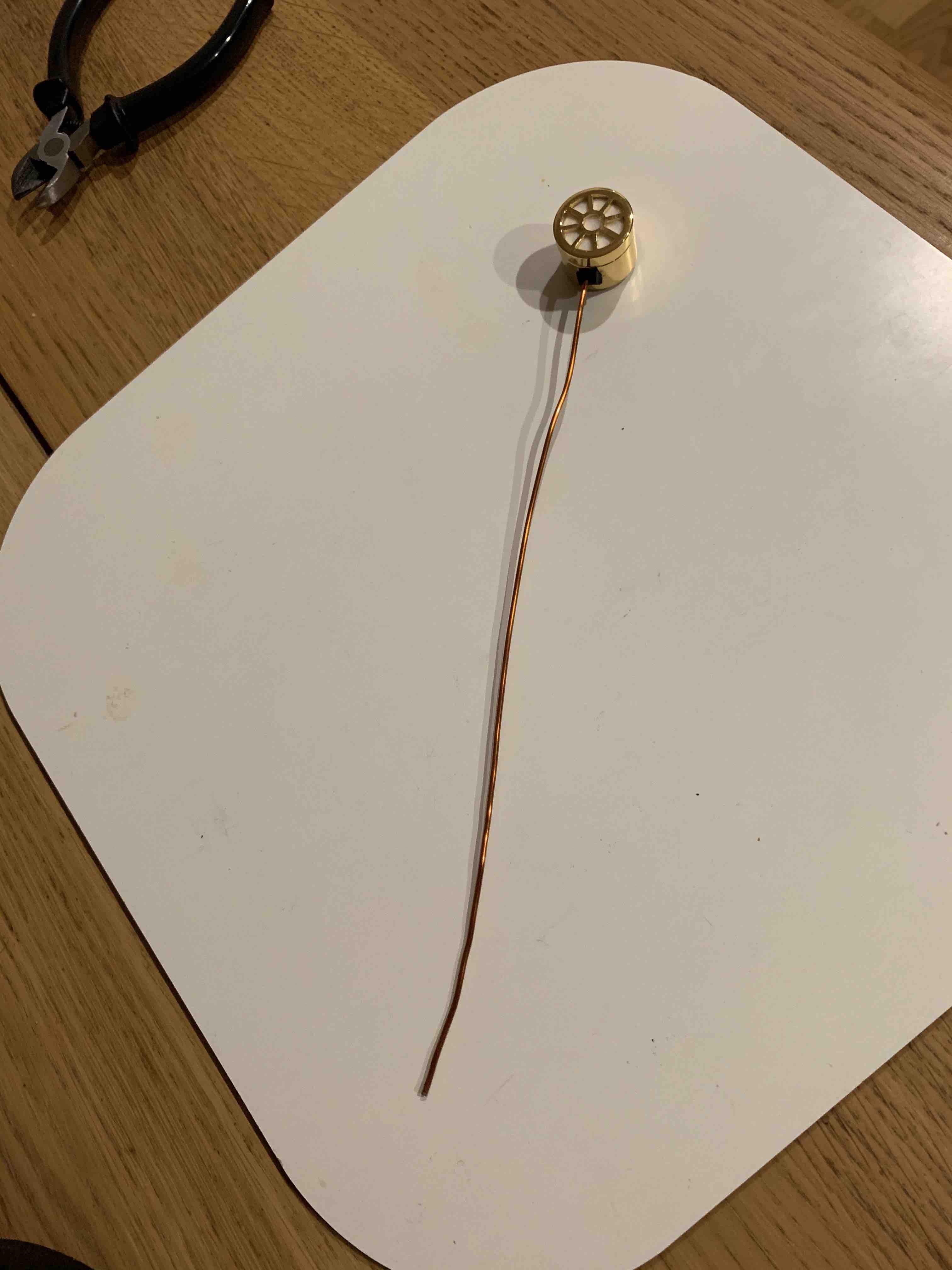
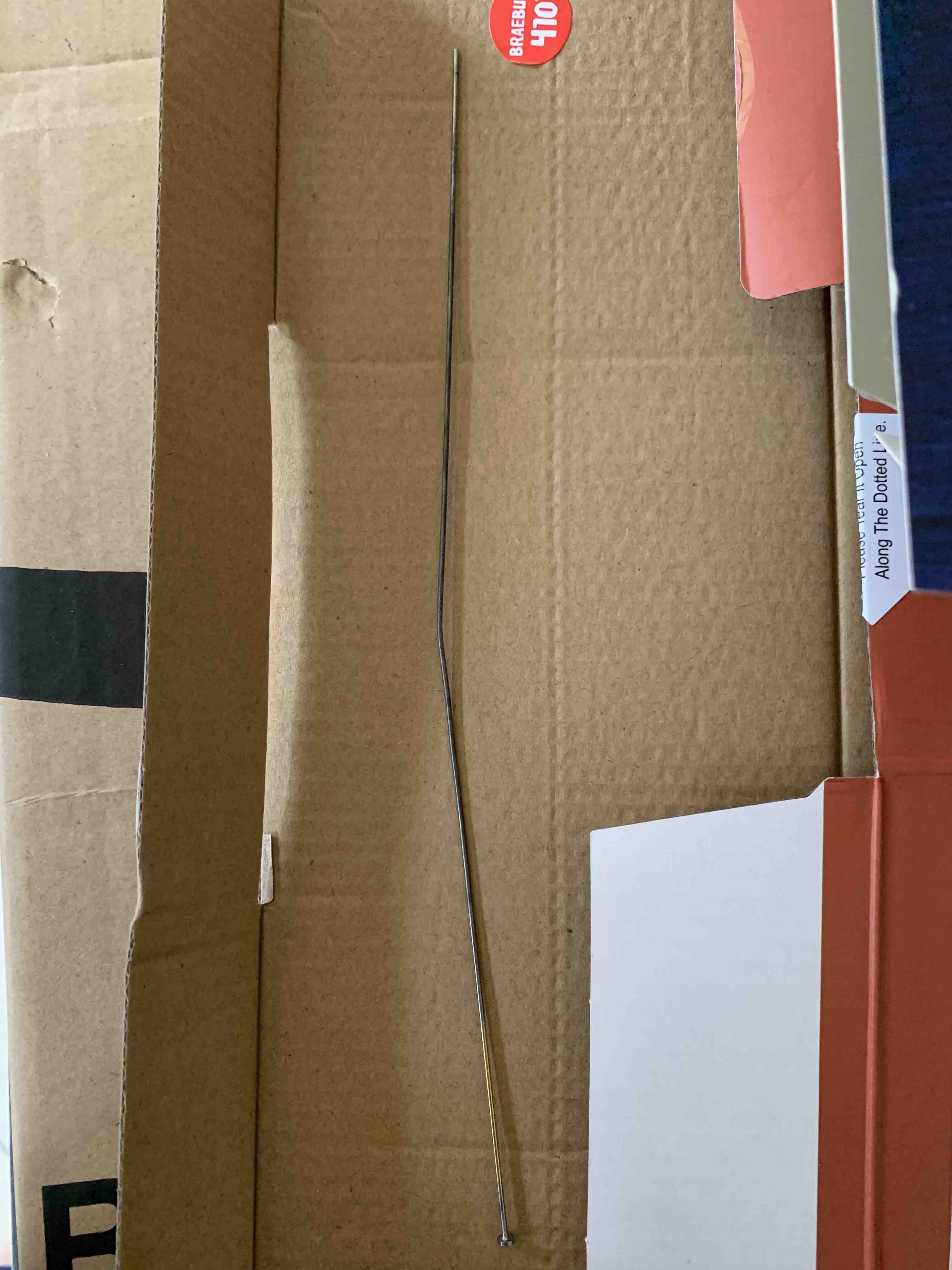
 Call me crazy, but the antenna that "The Thing" had was very thing and had a flattened head,
I again didn't know how I was going to make it at this point, so I had one made in a non-conductive
aluminium, the finish on the piece is terrible, and it's very easy to bend.
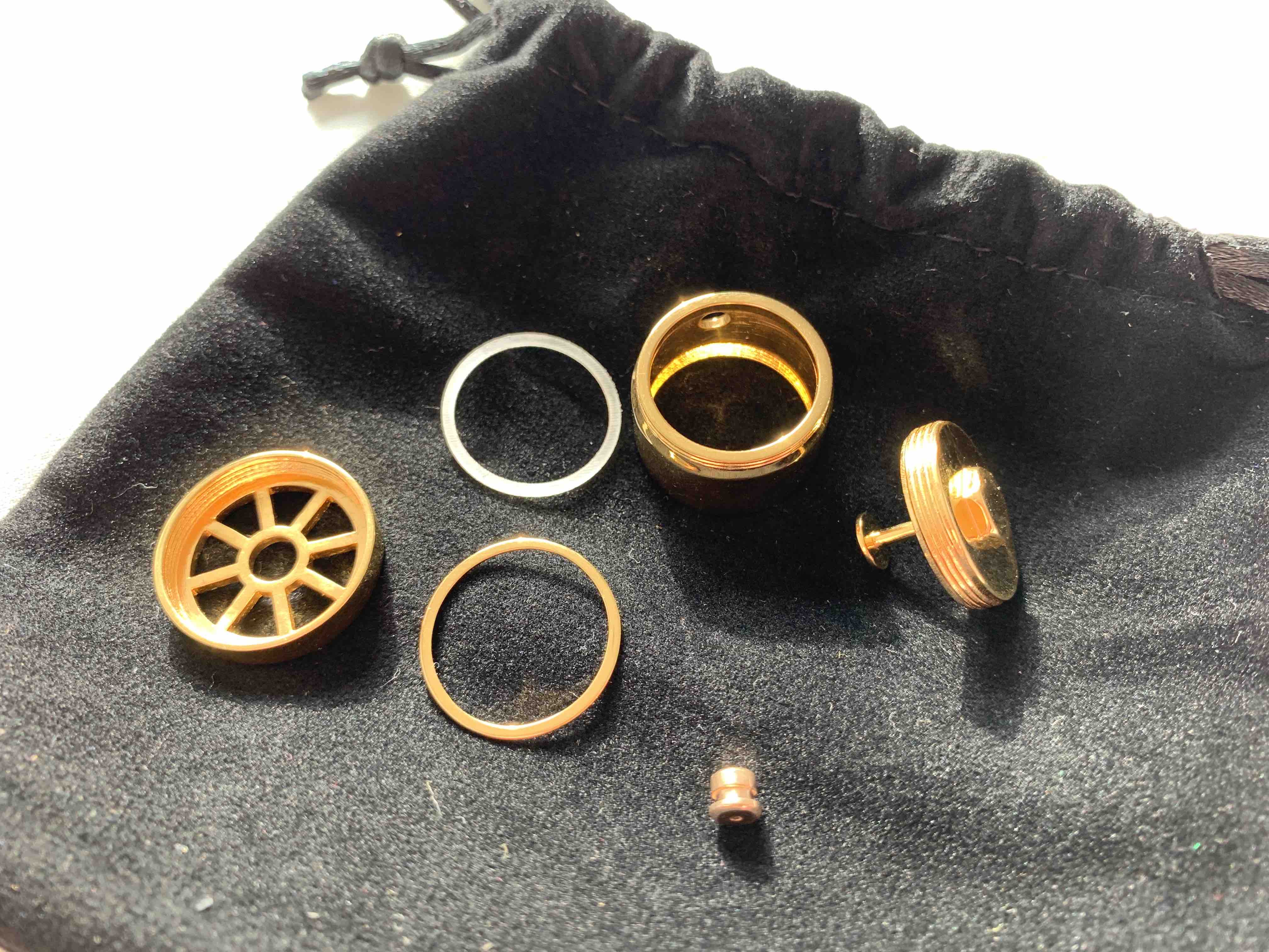
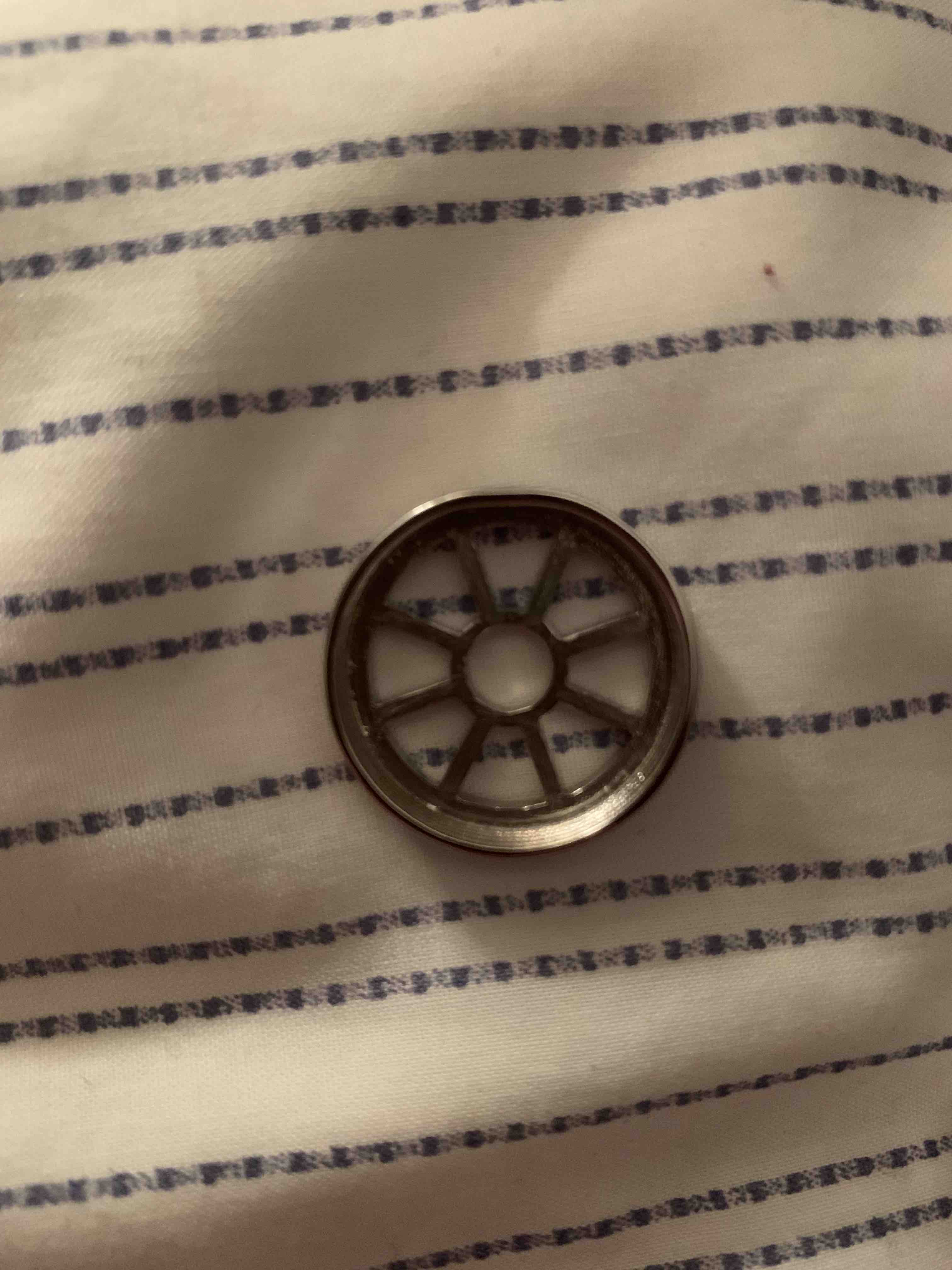
Note the units pieces screwed together great
Call me crazy, but the antenna that "The Thing" had was very thing and had a flattened head,
I again didn't know how I was going to make it at this point, so I had one made in a non-conductive
aluminium, the finish on the piece is terrible, and it's very easy to bend.
Note the units pieces screwed together great
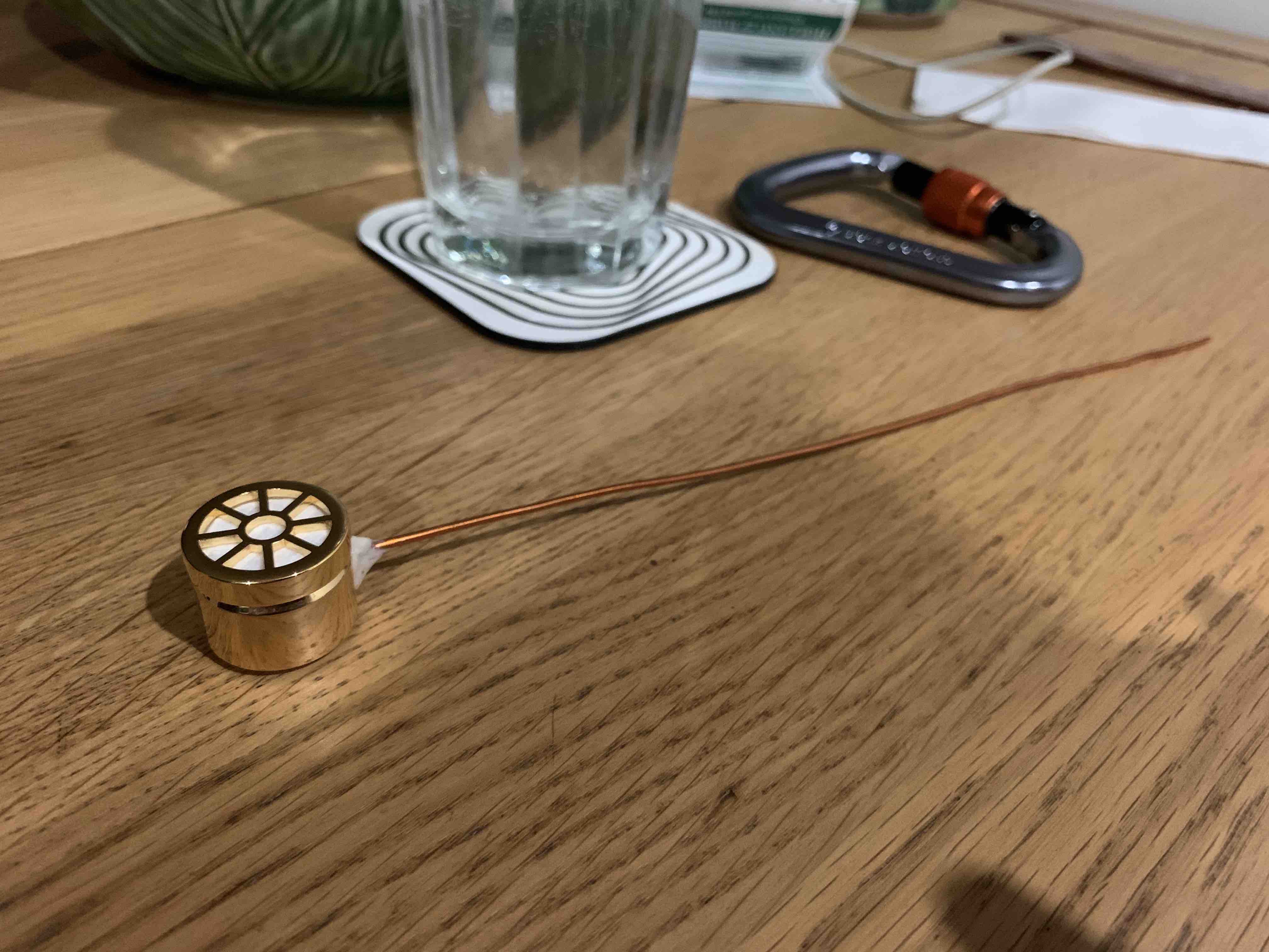 I added a material cover just to see how it looks, and tried and failed to bend a piece of
copper to fit my needs, it wasn't going to work.
I added a material cover just to see how it looks, and tried and failed to bend a piece of
copper to fit my needs, it wasn't going to work.
 In this picture you can see a piece of rubber where the grommet would go....it was from
a hand protector of a recycleable coffee cup
In this picture you can see a piece of rubber where the grommet would go....it was from
a hand protector of a recycleable coffee cup
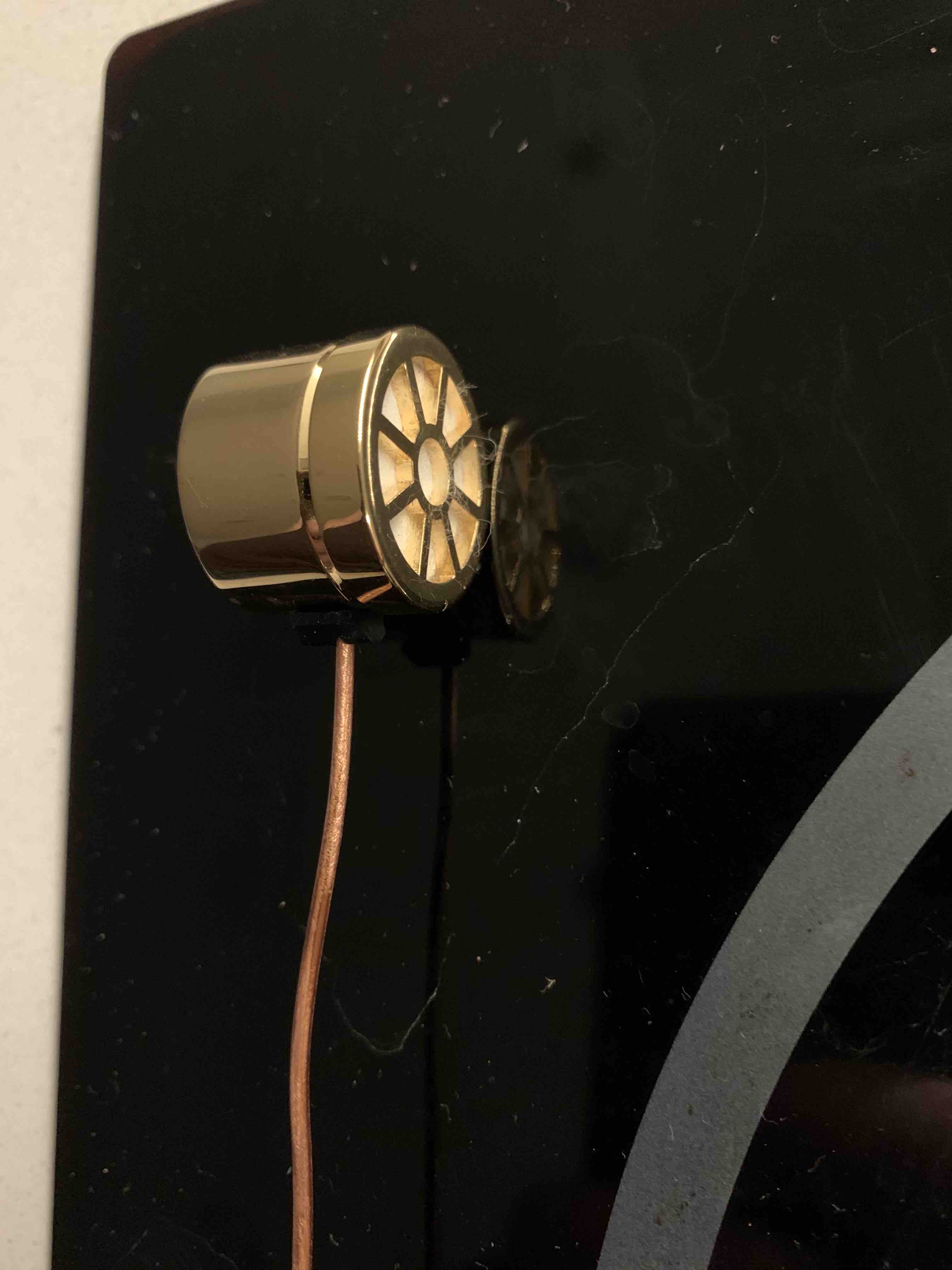 This photo shows how great the finish is on the unit, ignore the dirty oven top.
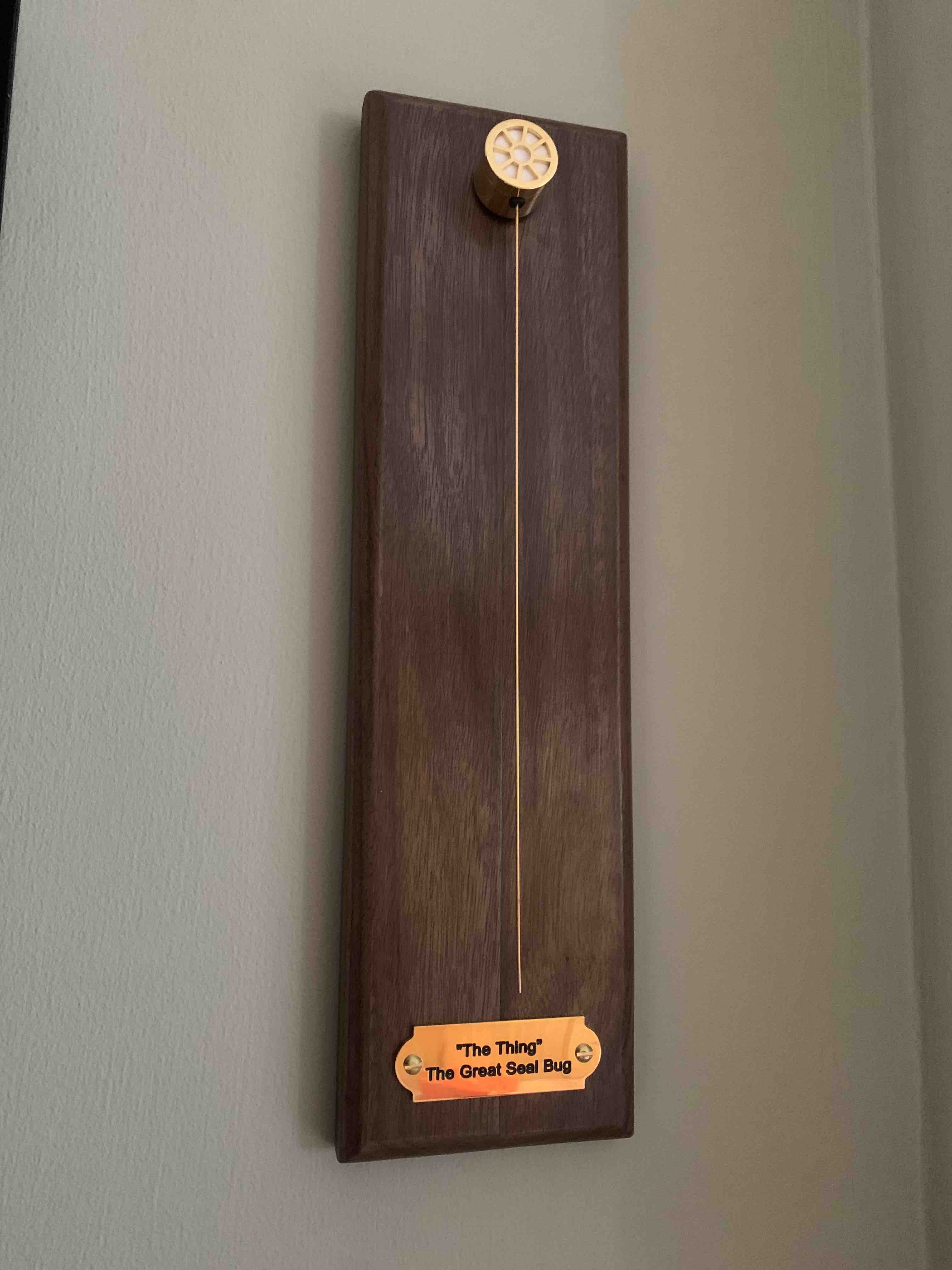
 It was around this time too I started to think about how I was going to present it.
The original was hidden inside the seal, but I wanted to show mine off. I wanted to show
the old with the new, maybe a bright plinth?
It was around this time too I started to think about how I was going to present it.
The original was hidden inside the seal, but I wanted to show mine off. I wanted to show
the old with the new, maybe a bright plinth?
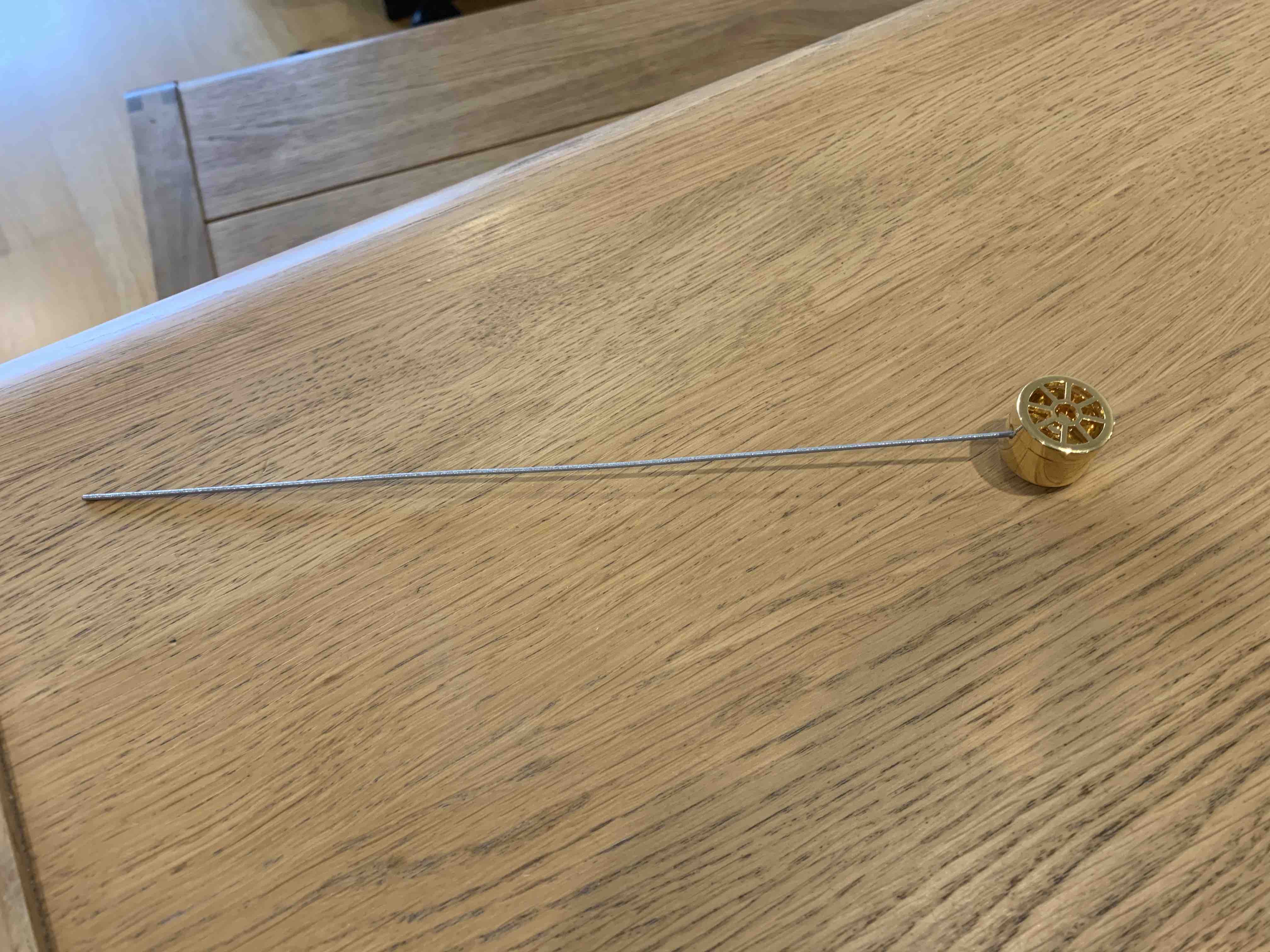
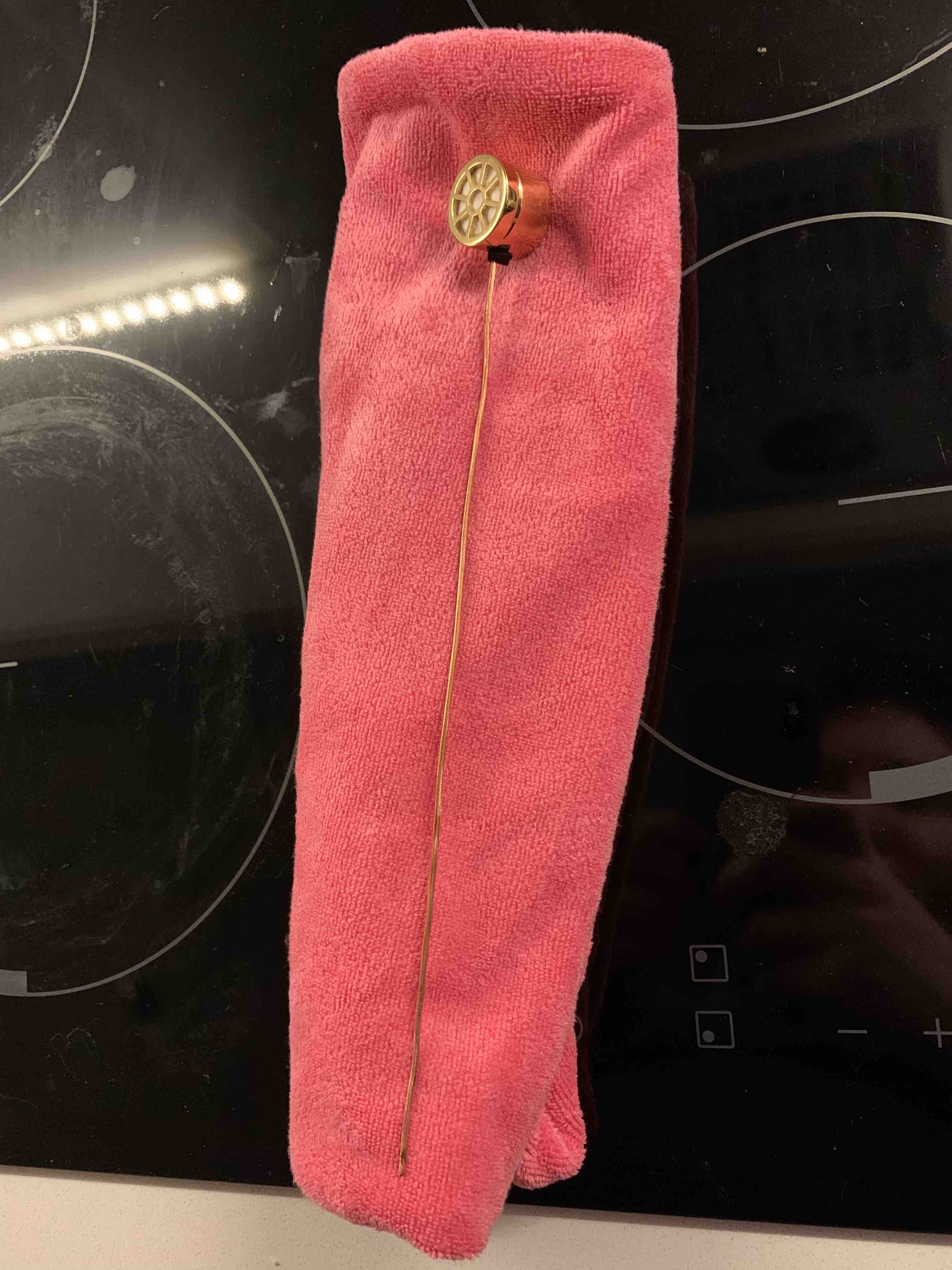
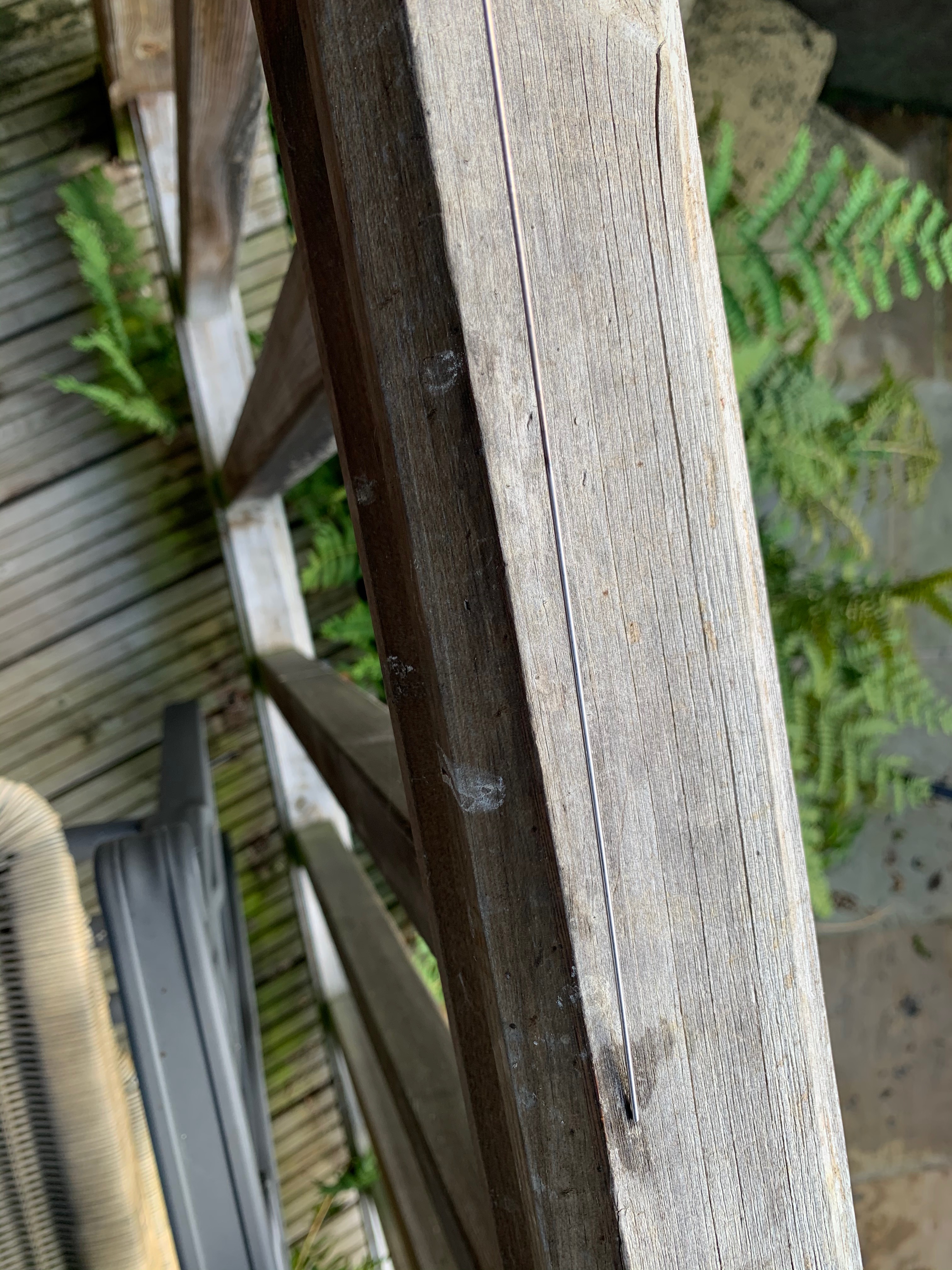
 This picture makes the cut as it feels warm, you can see how I've bent the copper rod
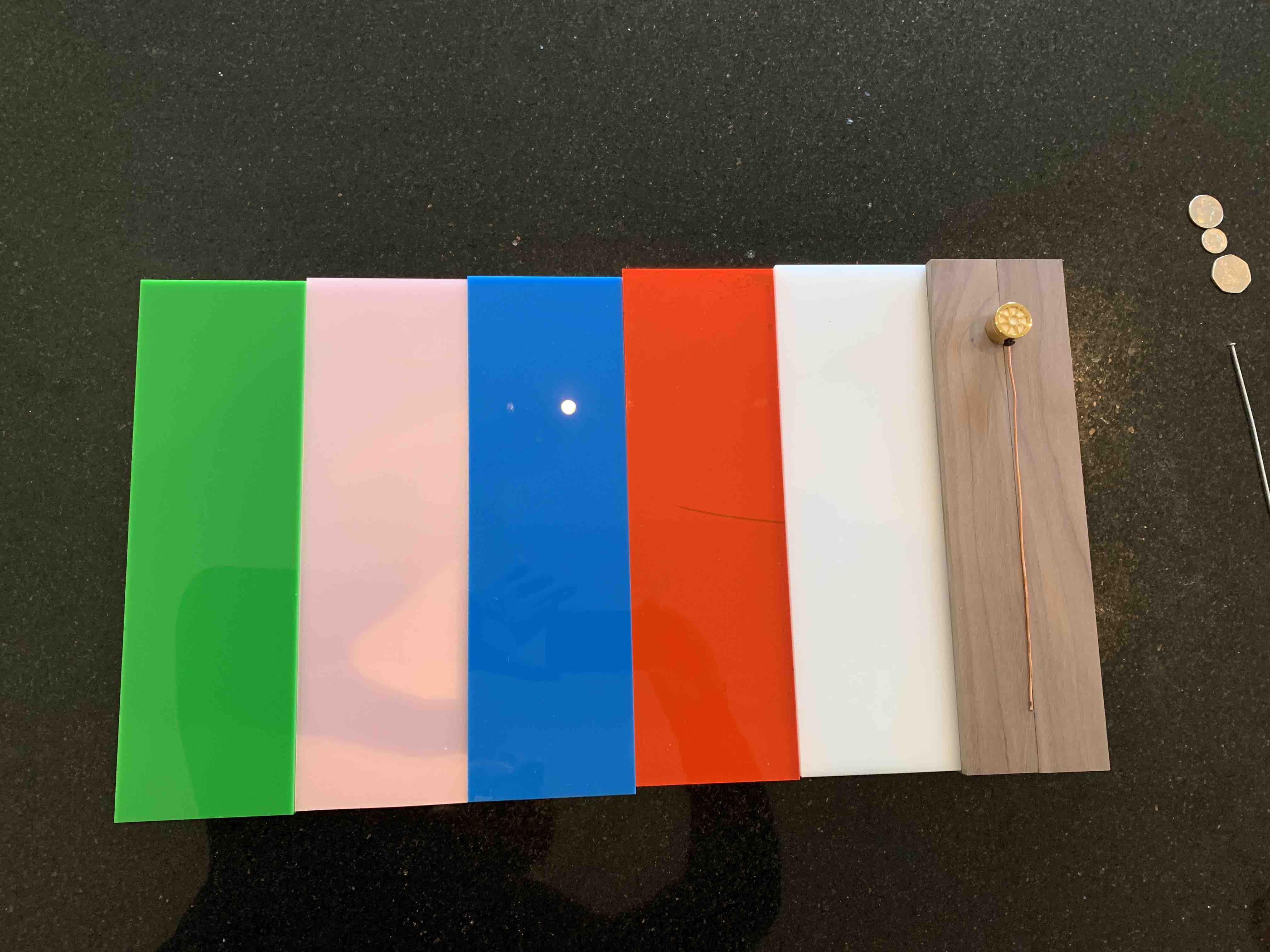 Plexiglass samples arrived, I really like the red, it's futuristic, walnut wood
also arrived, it was very thin though, so we joined it together with wood glue.
Plexiglass samples arrived, I really like the red, it's futuristic, walnut wood
also arrived, it was very thin though, so we joined it together with wood glue.
 I really wanted a fancy plaque to go at the bottom, maybe it should have a QR code?
Paper will do for now.
I really wanted a fancy plaque to go at the bottom, maybe it should have a QR code?
Paper will do for now.
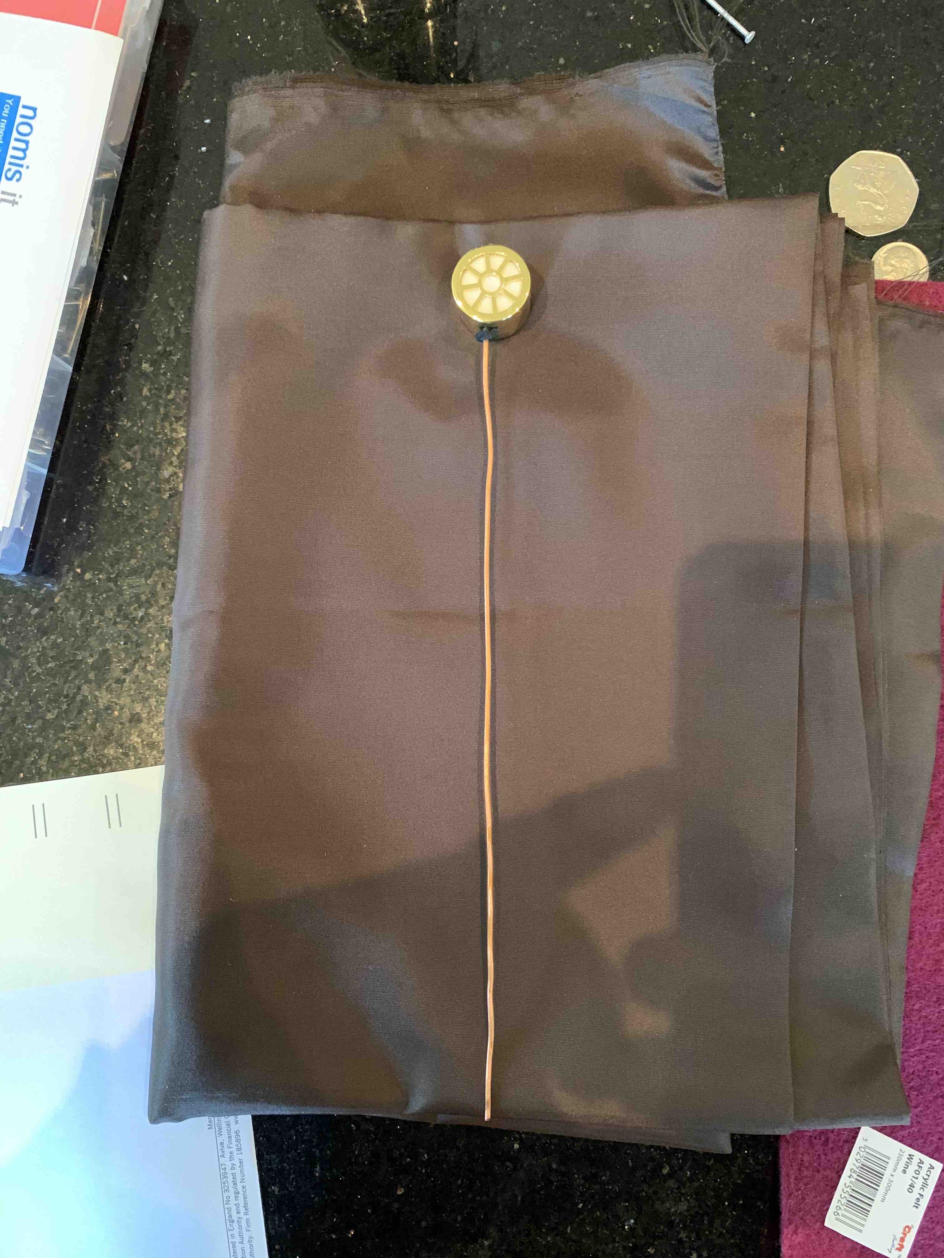
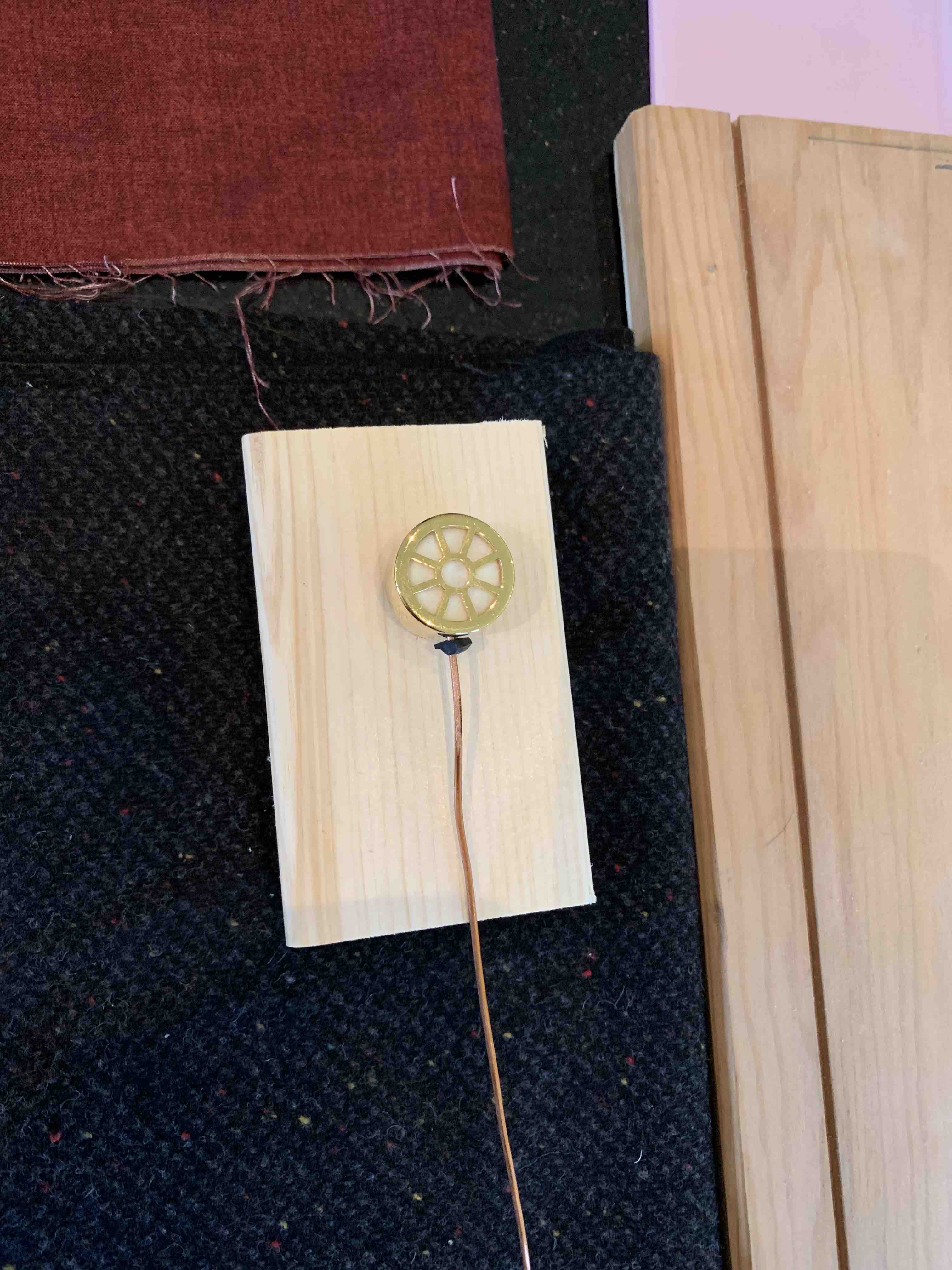
 I also wanted to try different materials for the plinth, here's a blue
 Here's a textured red
 A red/purple colour.
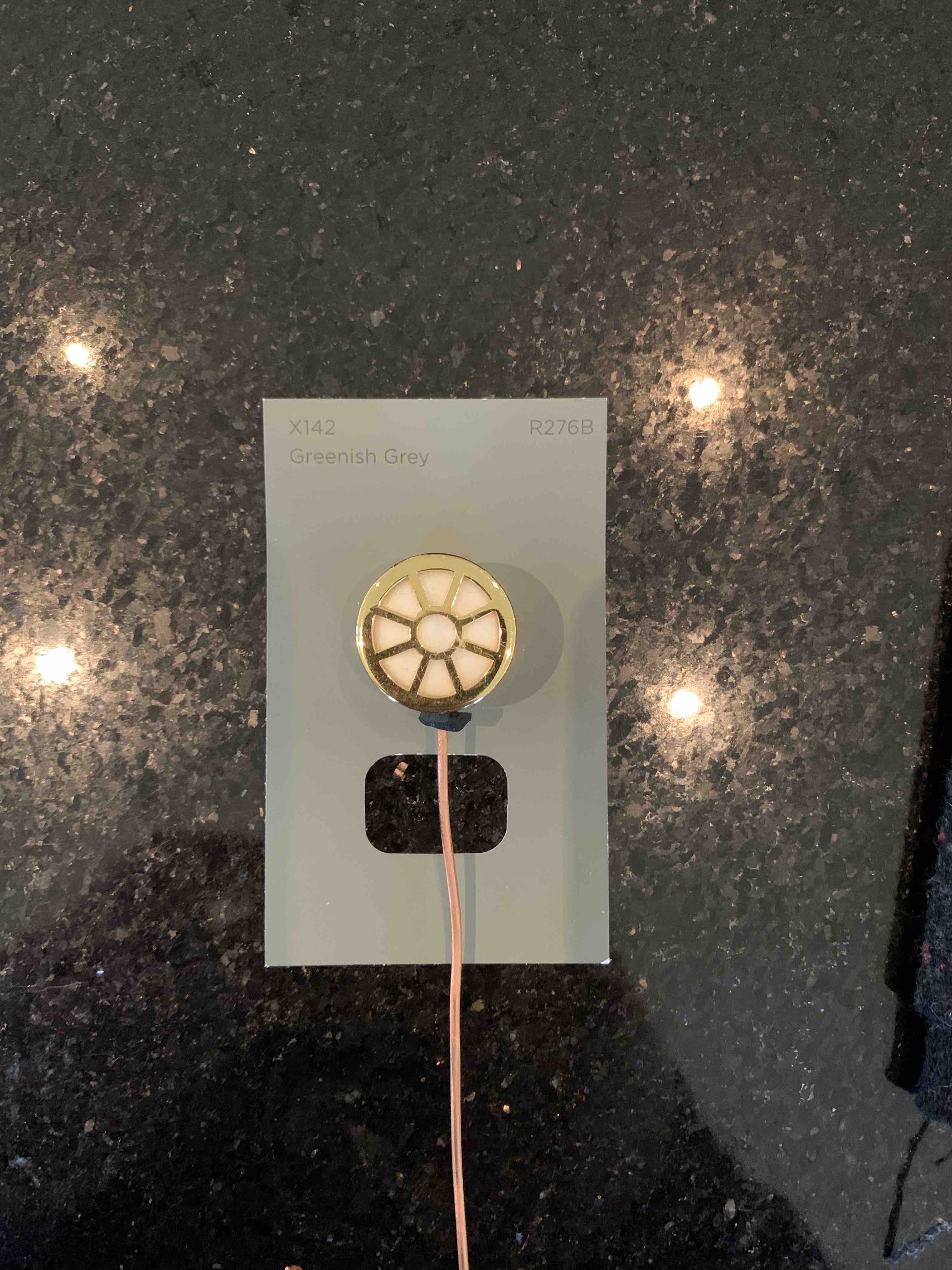
 A brown colour.
 Pine wood, an immediate dismissal from me
 Textured black
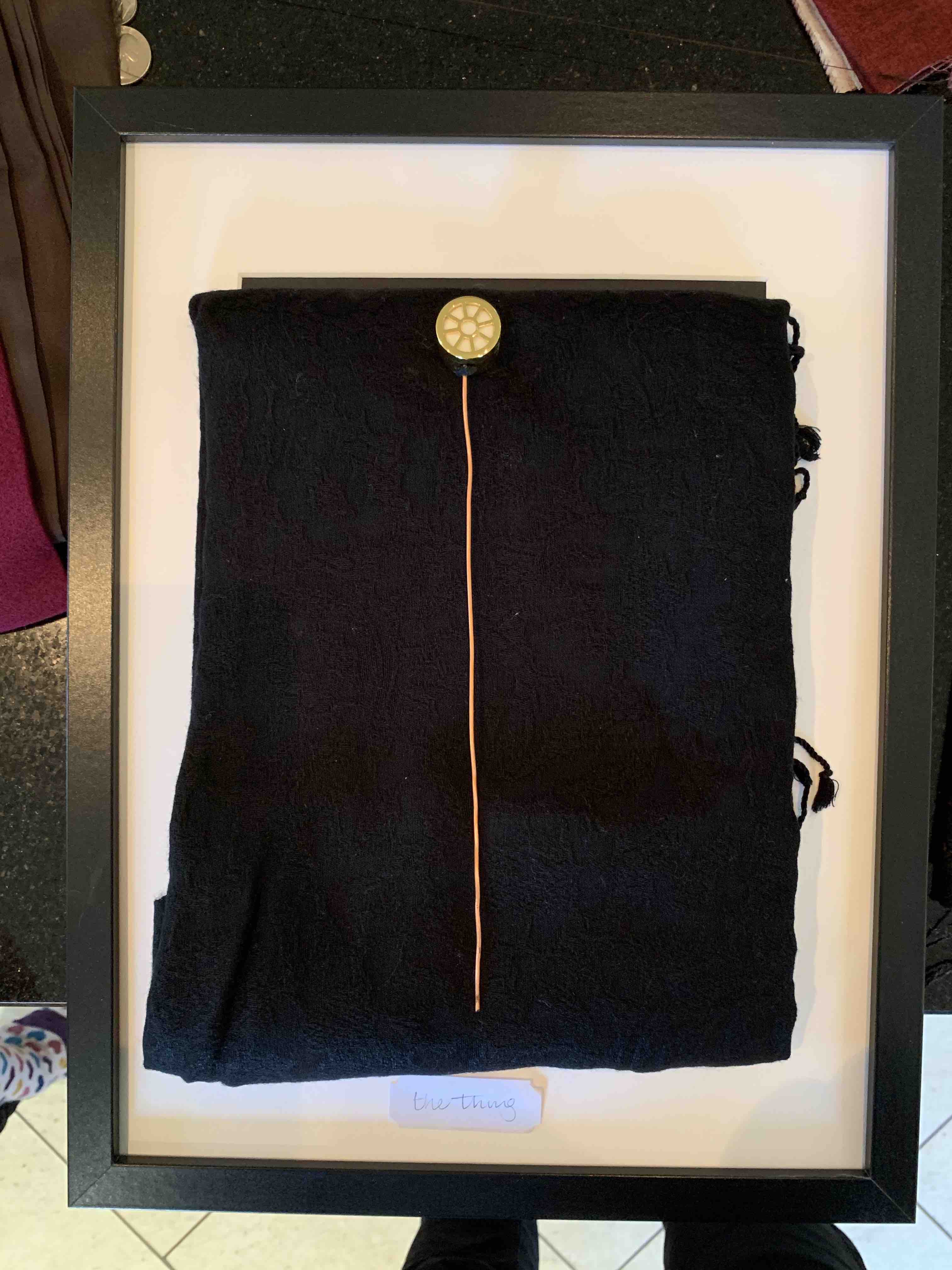 In this photo I decided to bring in a frame, should it be mounted in a frame?
 A green colour sample form somewhere found it's way into the mix.
 The wood was varnished as a test and also the edges were routed just to see
what sort of effects we could have, at this point, I'm not that happy with how
it came out
The wood was varnished as a test and also the edges were routed just to see
what sort of effects we could have, at this point, I'm not that happy with how
it came out
 A plaque sample arrived, I think the plaque looks great.
 Checking the aluminium 3d printed antenna against an unknown piece of metal and the copper
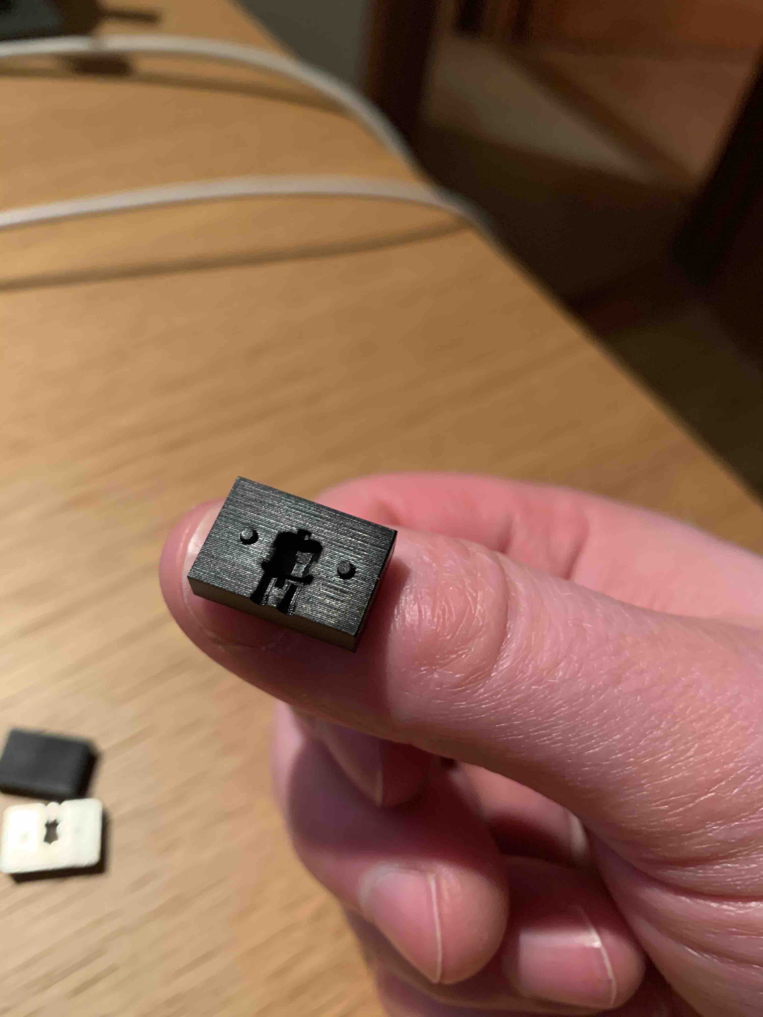 An injection mold made of PA12 Rigid polyurethane, this was very expensive :-/
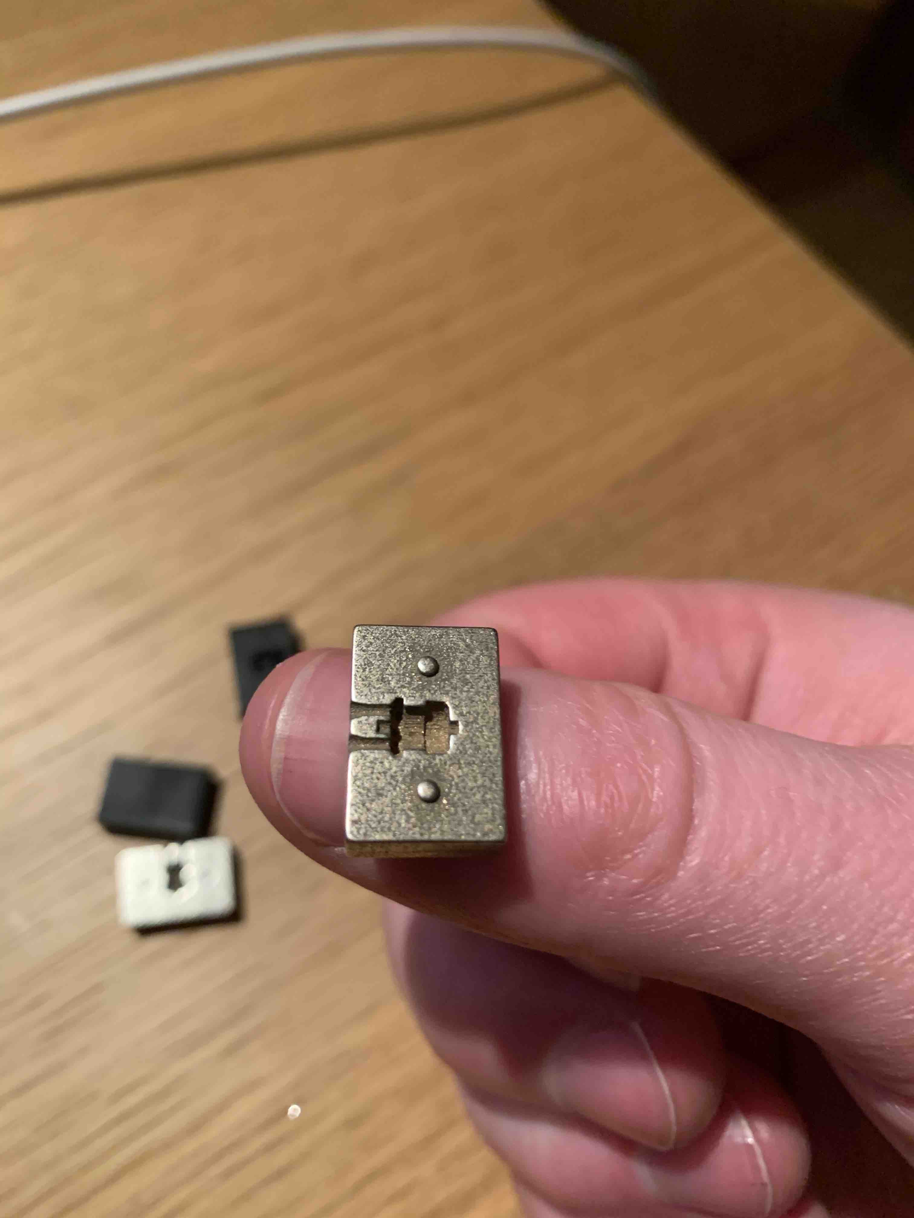 An injection mold made of polished bronzed silver, I was amazed that this could be printed
at all, the main issue straight away was that the locking keys had rounded off and were not
sharp, this meant that the two halves would not fit together, I tried to fix this, but in the
end just ended up sanding them clean off
An injection mold made of polished bronzed silver, I was amazed that this could be printed
at all, the main issue straight away was that the locking keys had rounded off and were not
sharp, this meant that the two halves would not fit together, I tried to fix this, but in the
end just ended up sanding them clean off
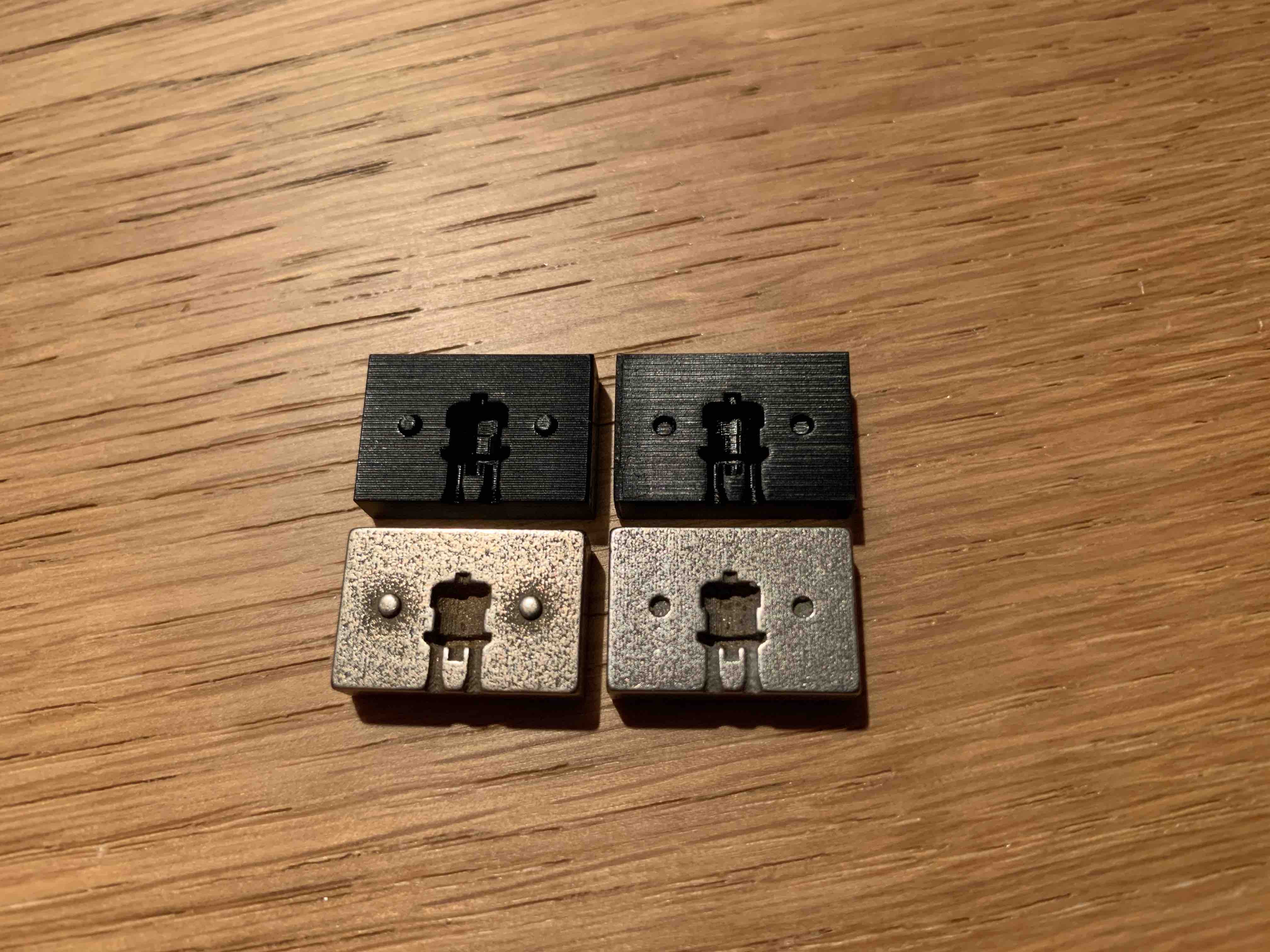 A side-by-side comparison of the two injection molding blocks
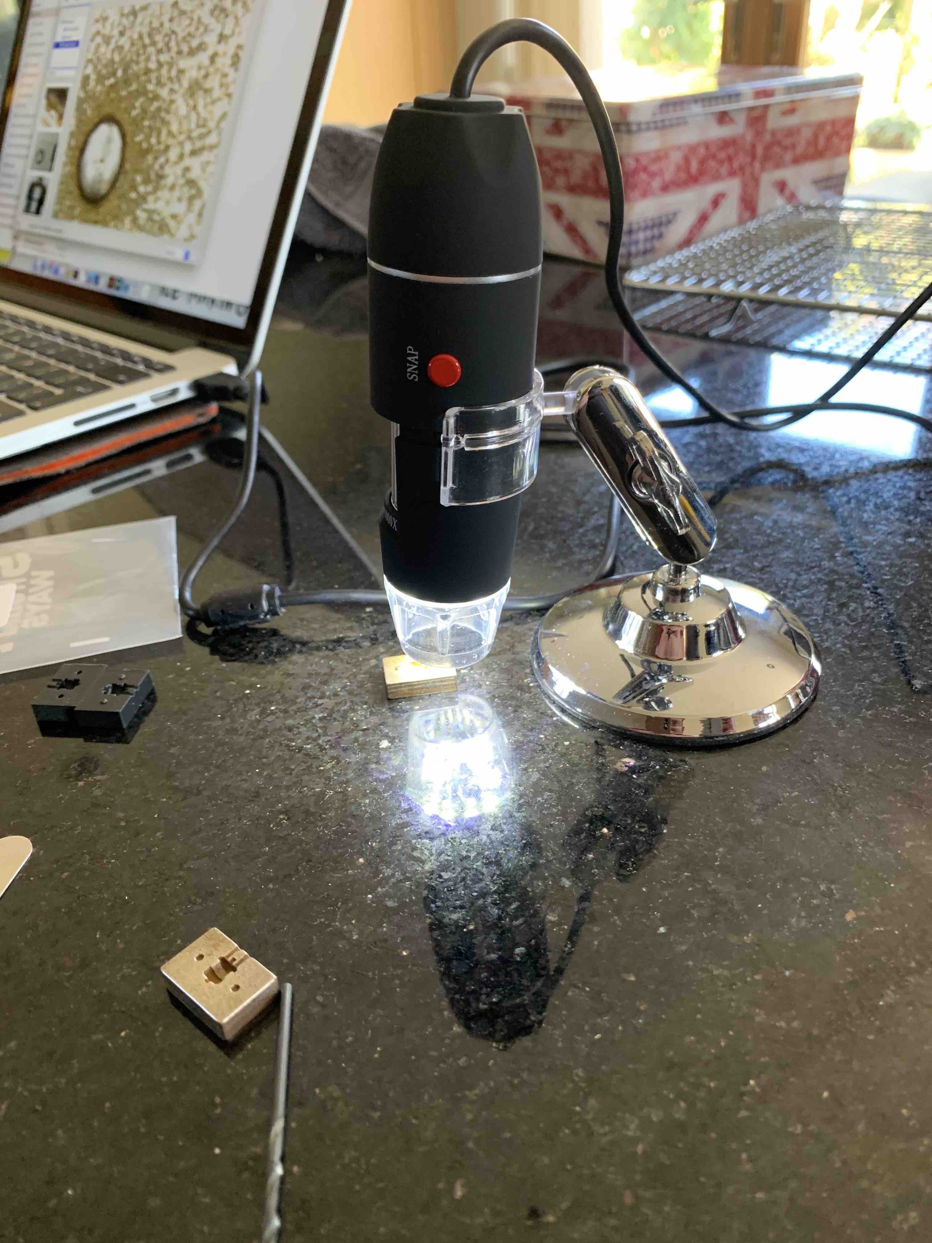 I wasn't sure of the detail of the molds, so I purchased an inexpensive microscope
from ebay to have a look
I wasn't sure of the detail of the molds, so I purchased an inexpensive microscope
from ebay to have a look
 When I say Injection molding, I mean Injection molding.
These parts are so small, and the amount of rubber I was going to make also tiny
When I say Injection molding, I mean Injection molding.
These parts are so small, and the amount of rubber I was going to make also tiny
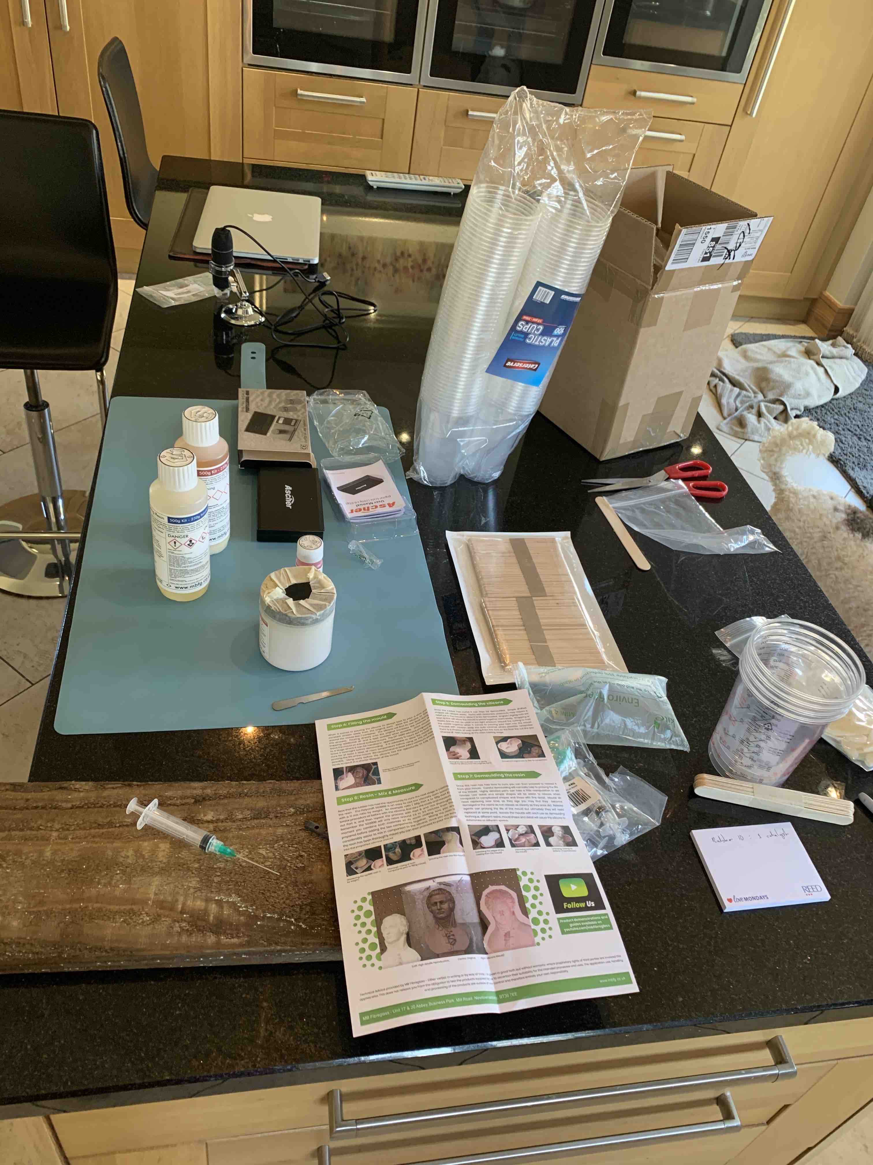 Up until this point in life, I'd never made a mold, or played with silicon rubber, I was
about to get messy
Up until this point in life, I'd never made a mold, or played with silicon rubber, I was
about to get messy
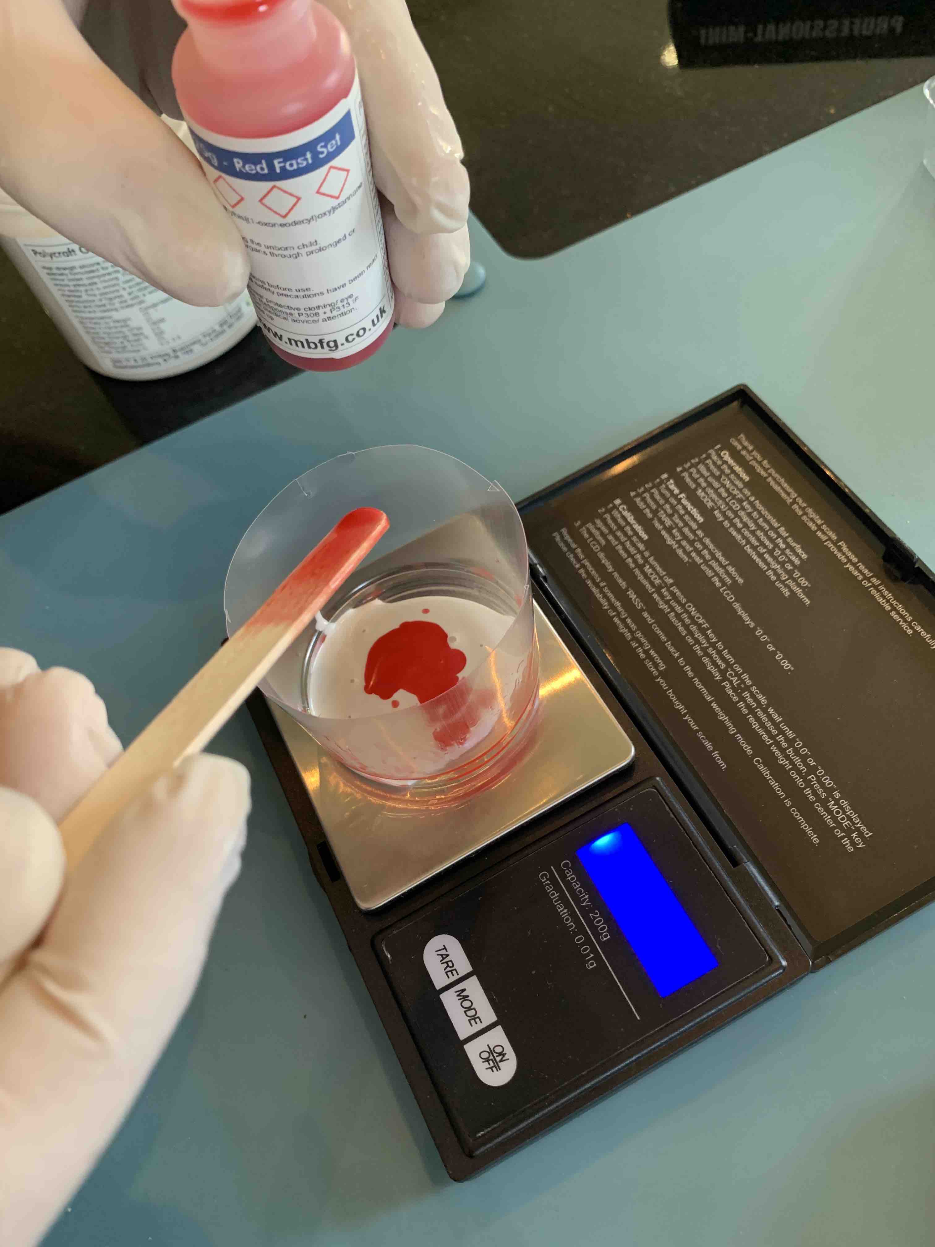 Adding the catalyst to the base
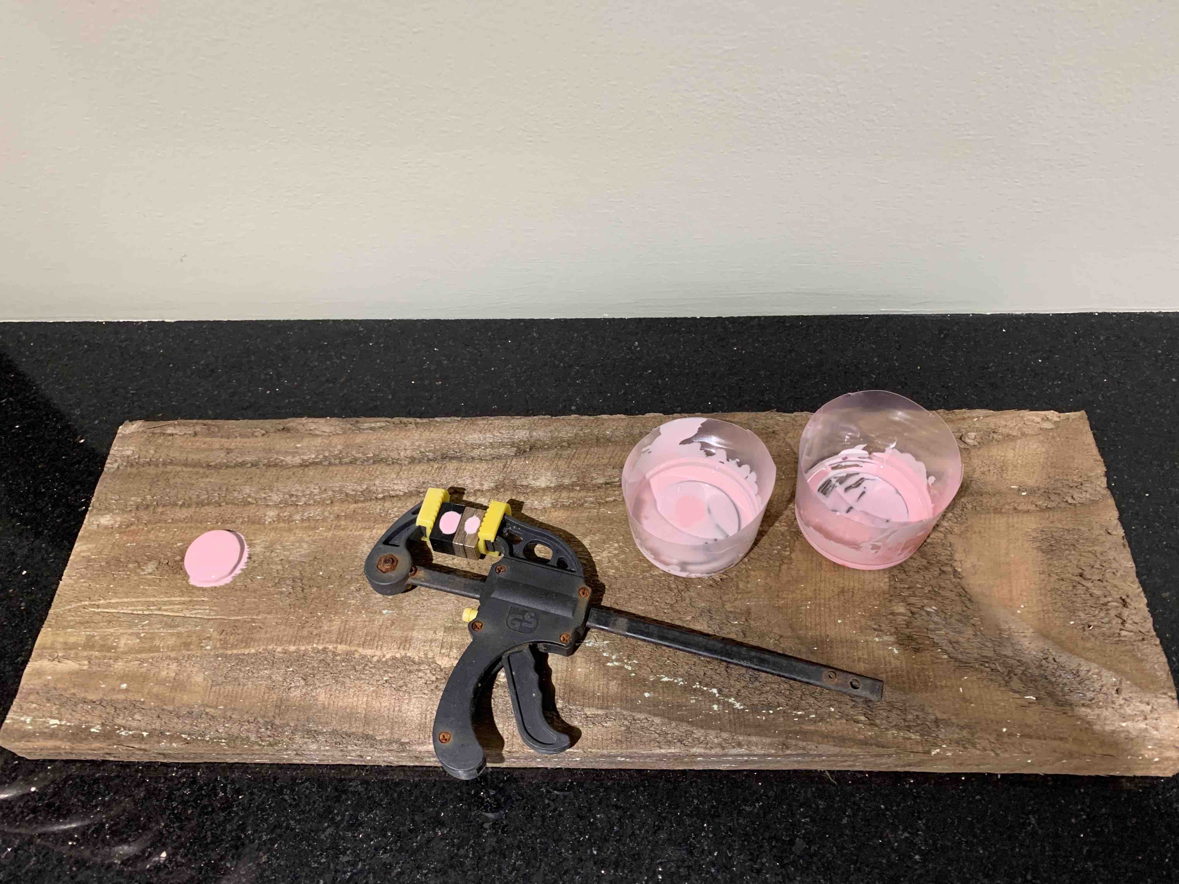
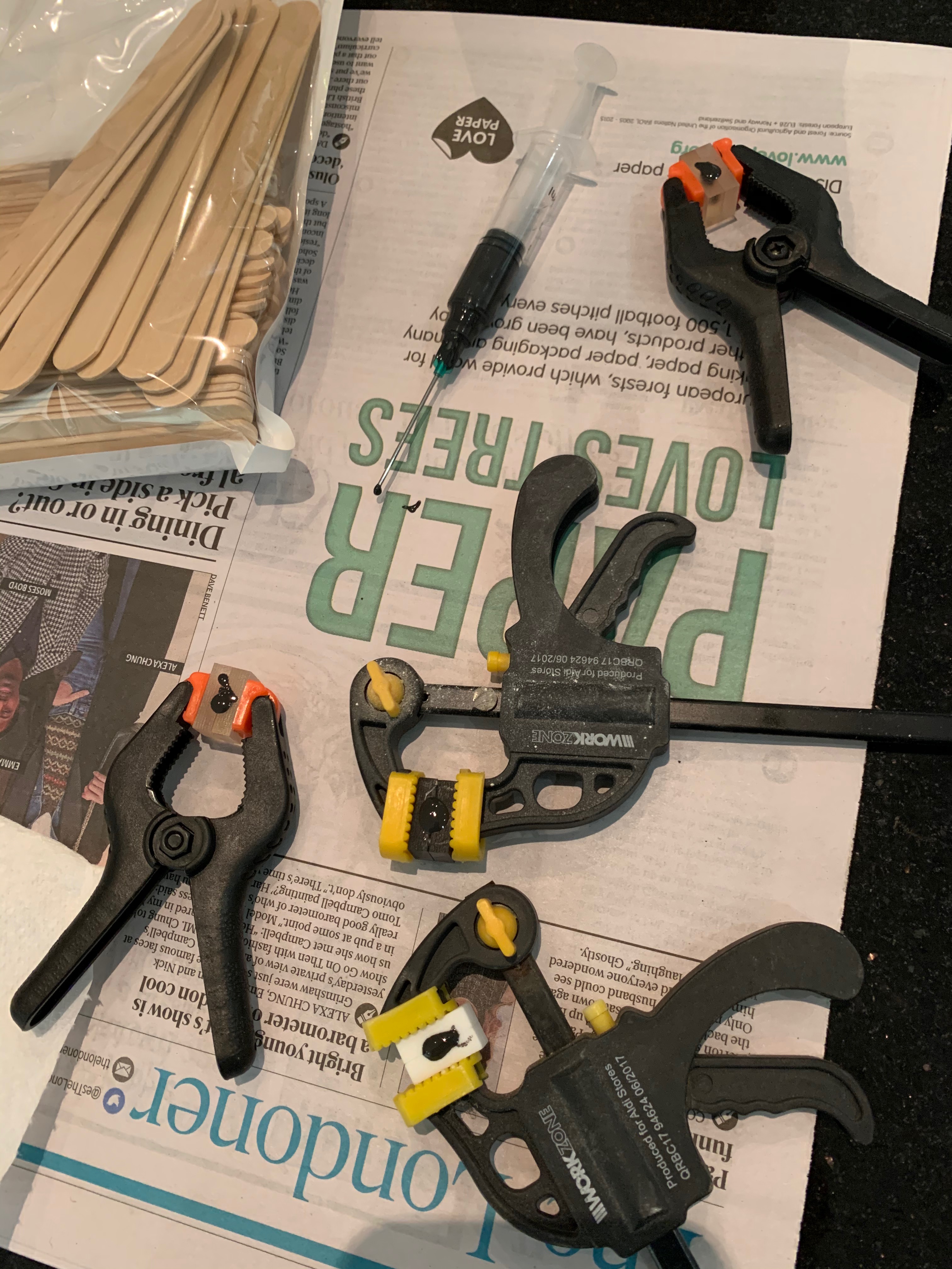
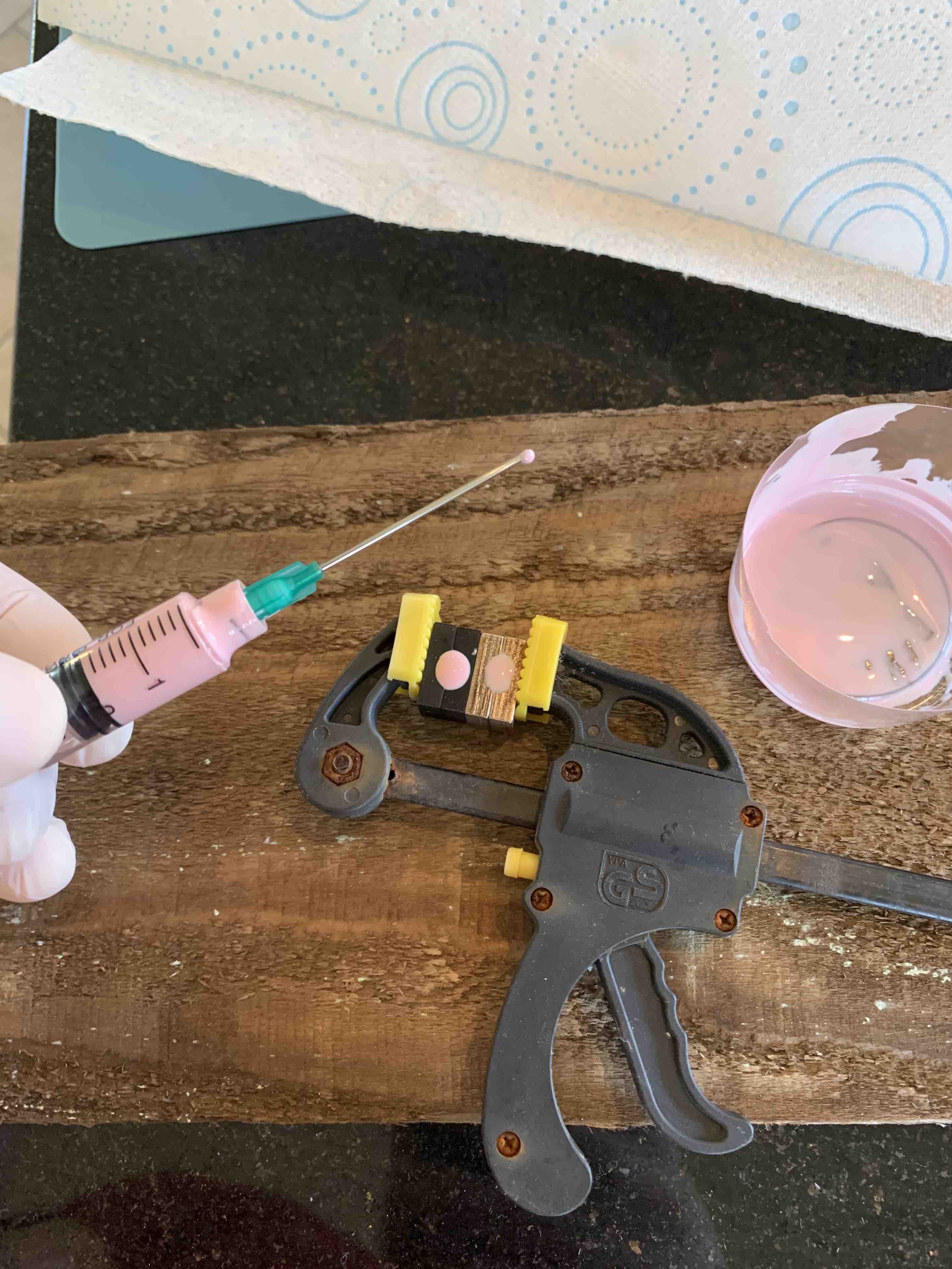 Silicon rubber in the syringe
 After mixing up some silicon rubber, sucking it up into a syringe and then squirting it
into a mold, it actually took quite a bit pressure
After mixing up some silicon rubber, sucking it up into a syringe and then squirting it
into a mold, it actually took quite a bit pressure
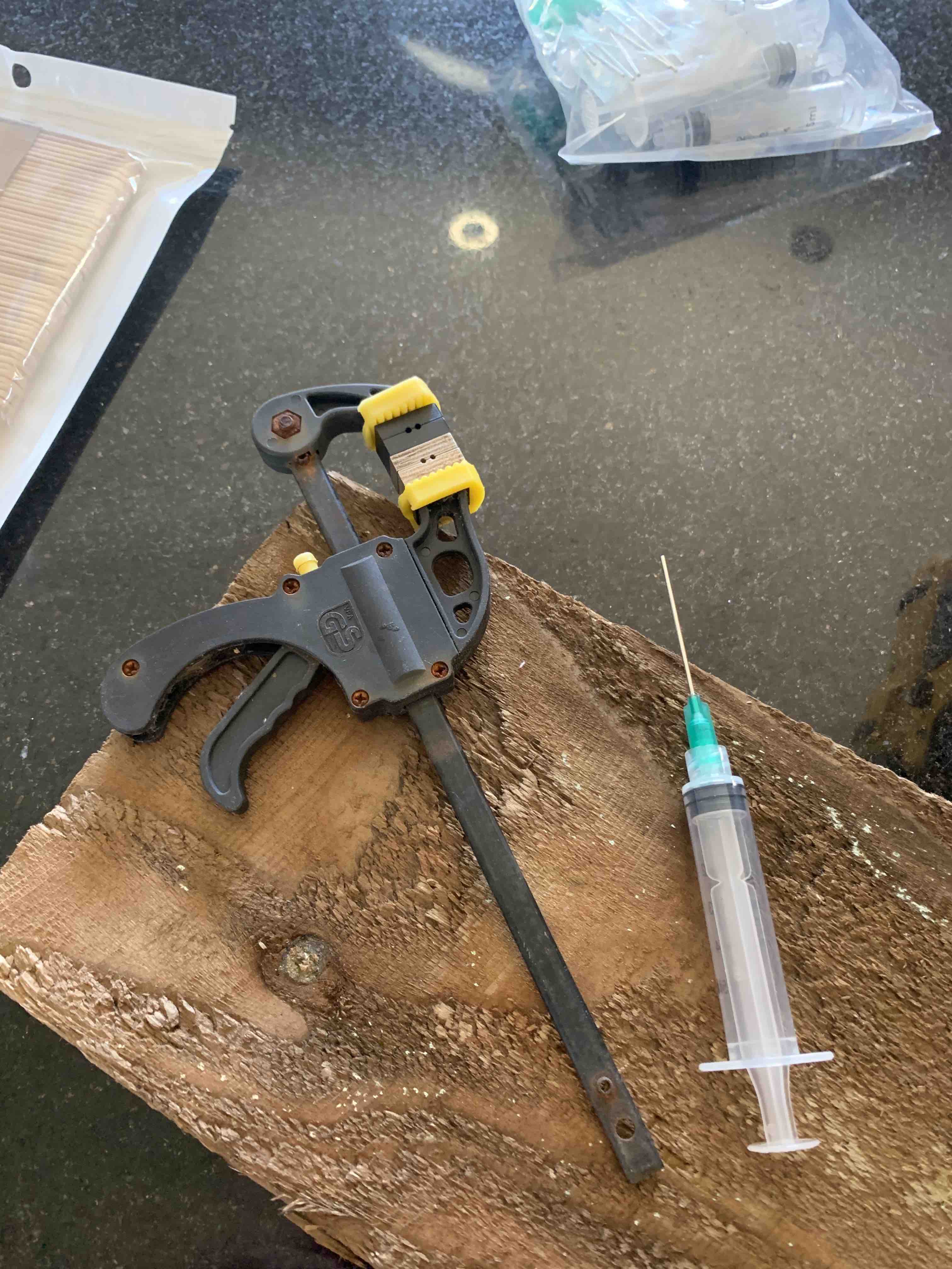
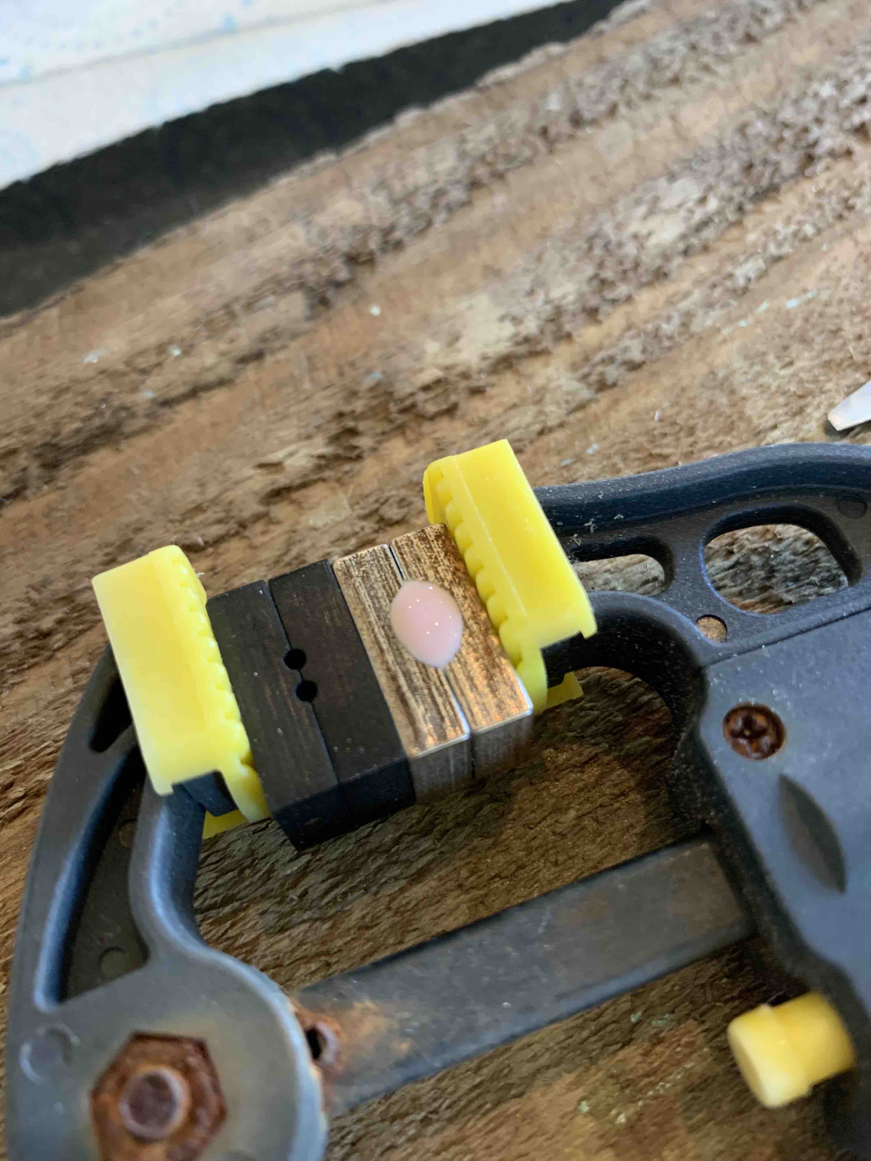
 Using a micro clamp to hold the molds in place, I'll come back tomorrow to see how it sets
 About to break open the first mold (metal)
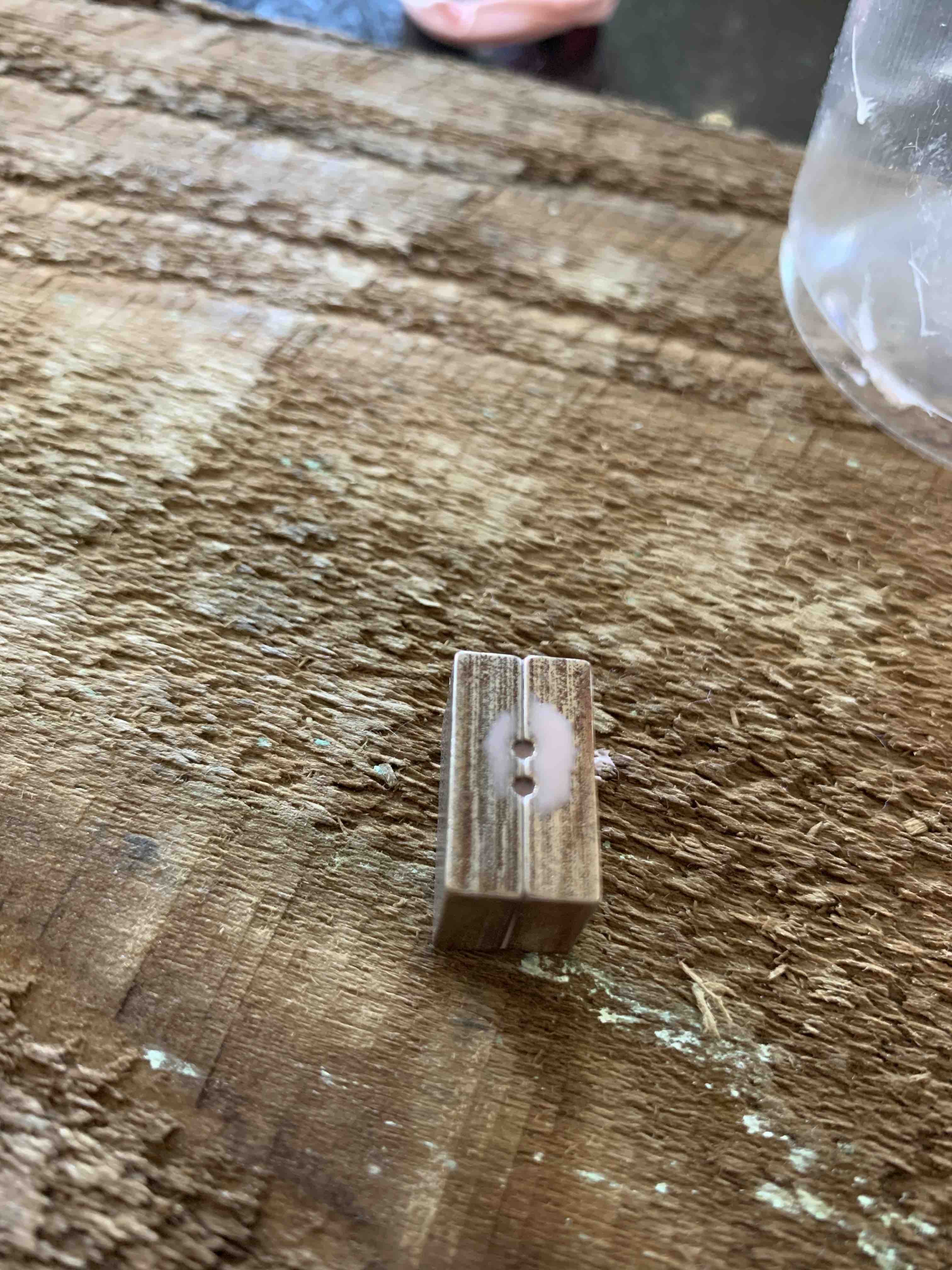
 Succes! Well, kind of, I didn't 3d print the piece that goes in the middle of the mold,
at this scale, it's just really small so I forego it going forward
Succes! Well, kind of, I didn't 3d print the piece that goes in the middle of the mold,
at this scale, it's just really small so I forego it going forward
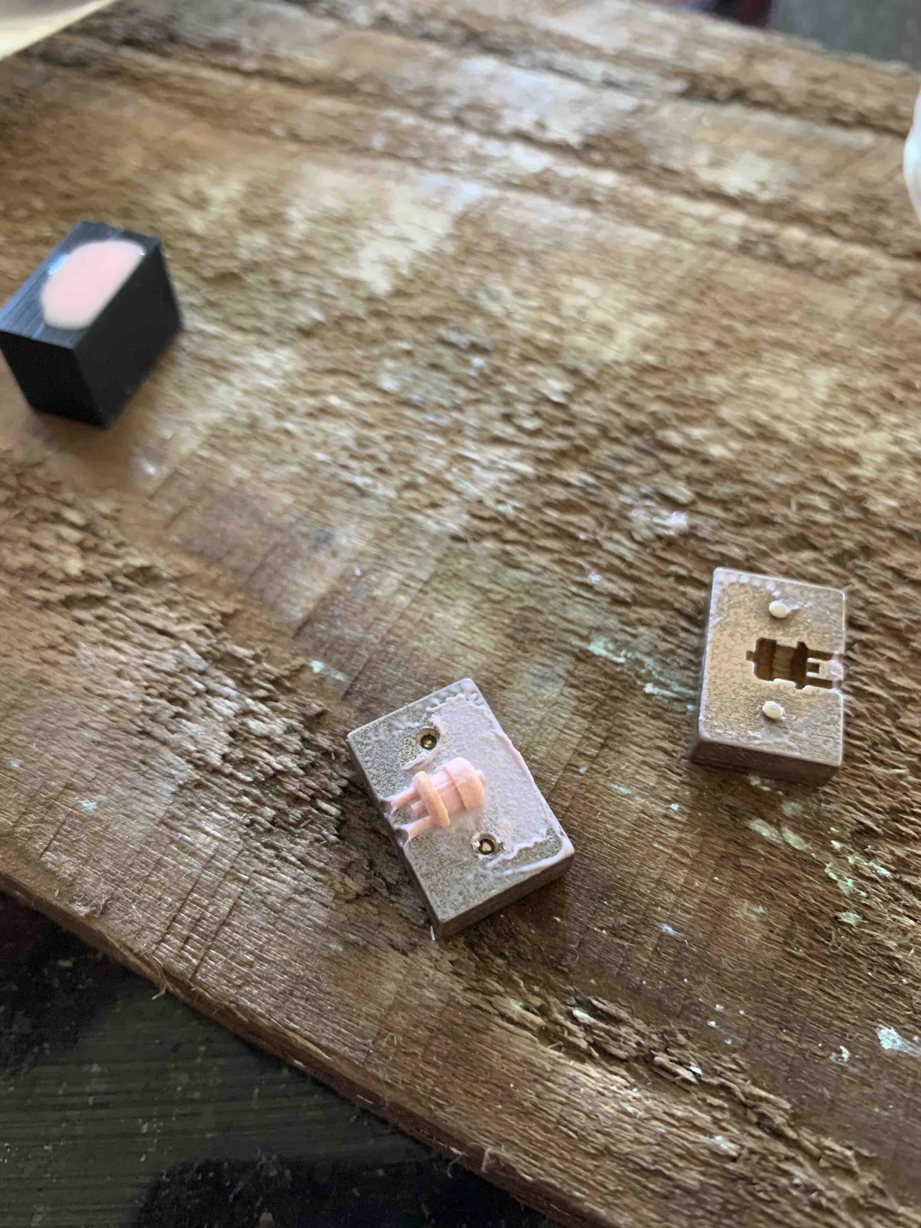
 The grommet from the PA12 mold has higher resolution
 Checking to see if the grommet fits
 Two sample parts arrive from China.
I was trying to figure out how this antenna could be made, 3D printing
wasn't an option as it's too expensive and it wouldn't fit inside the printer.
I posted on upwork for someone to produce me one, maybe someone had a watchmakers lathe?
It wasn't until about a week later when a Chinese company posted and said why I don't I just
press forge it....my mind was blown
Two sample parts arrive from China.
I was trying to figure out how this antenna could be made, 3D printing
wasn't an option as it's too expensive and it wouldn't fit inside the printer.
I posted on upwork for someone to produce me one, maybe someone had a watchmakers lathe?
It wasn't until about a week later when a Chinese company posted and said why I don't I just
press forge it....my mind was blown
 I couldn't just buy one antenna, I had to buy a bulk load of 500
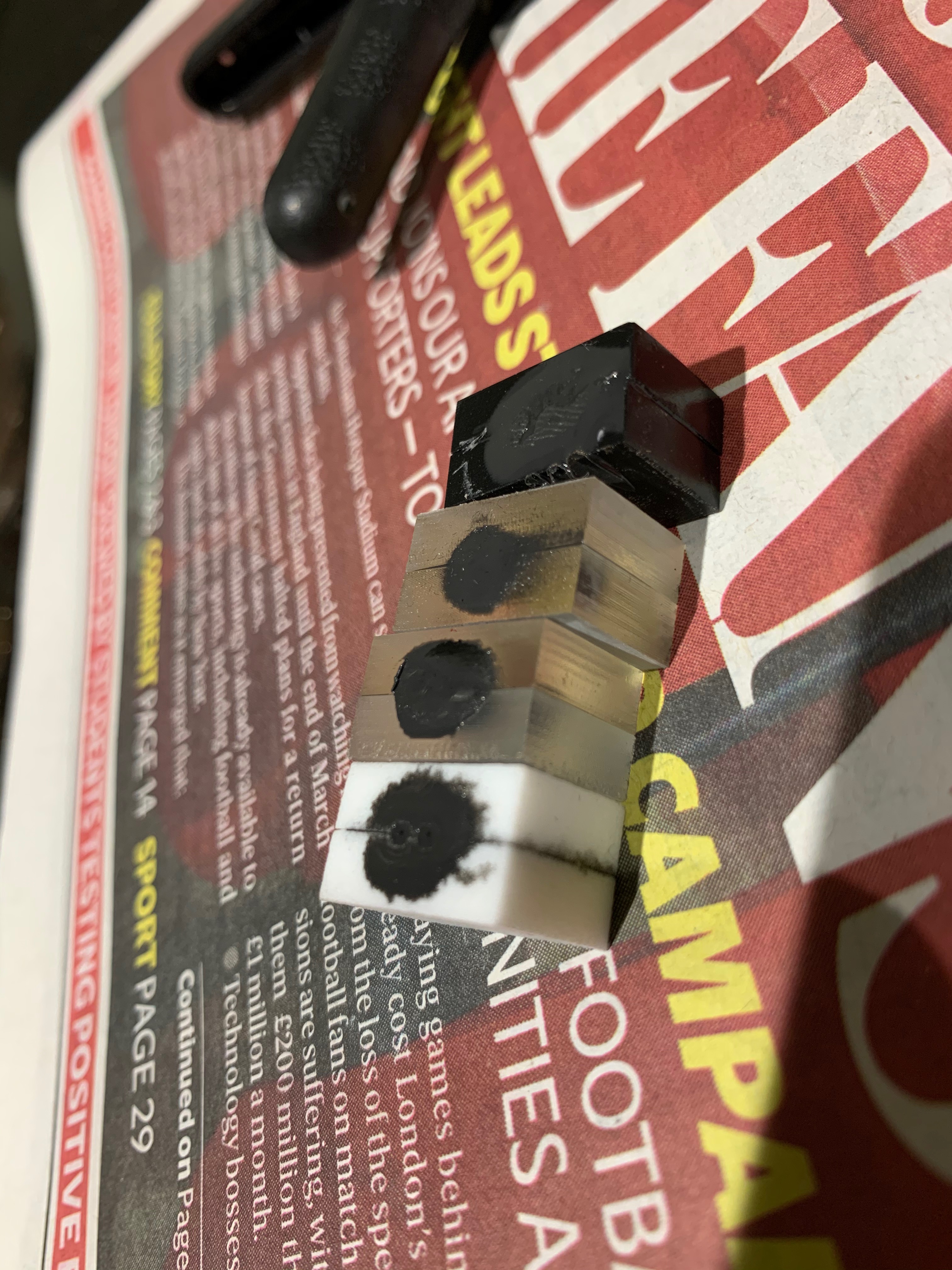
 I was experimenting with different materials, this one is silver.
The lost wax casting process on this one failed.
I was experimenting with different materials, this one is silver.
The lost wax casting process on this one failed.
 The steel antennas need to be golden, however, I can't just gold plate these apparently
they have to be nickel plated first, so we're just cleaning off any excess oil.
The steel antennas need to be golden, however, I can't just gold plate these apparently
they have to be nickel plated first, so we're just cleaning off any excess oil.
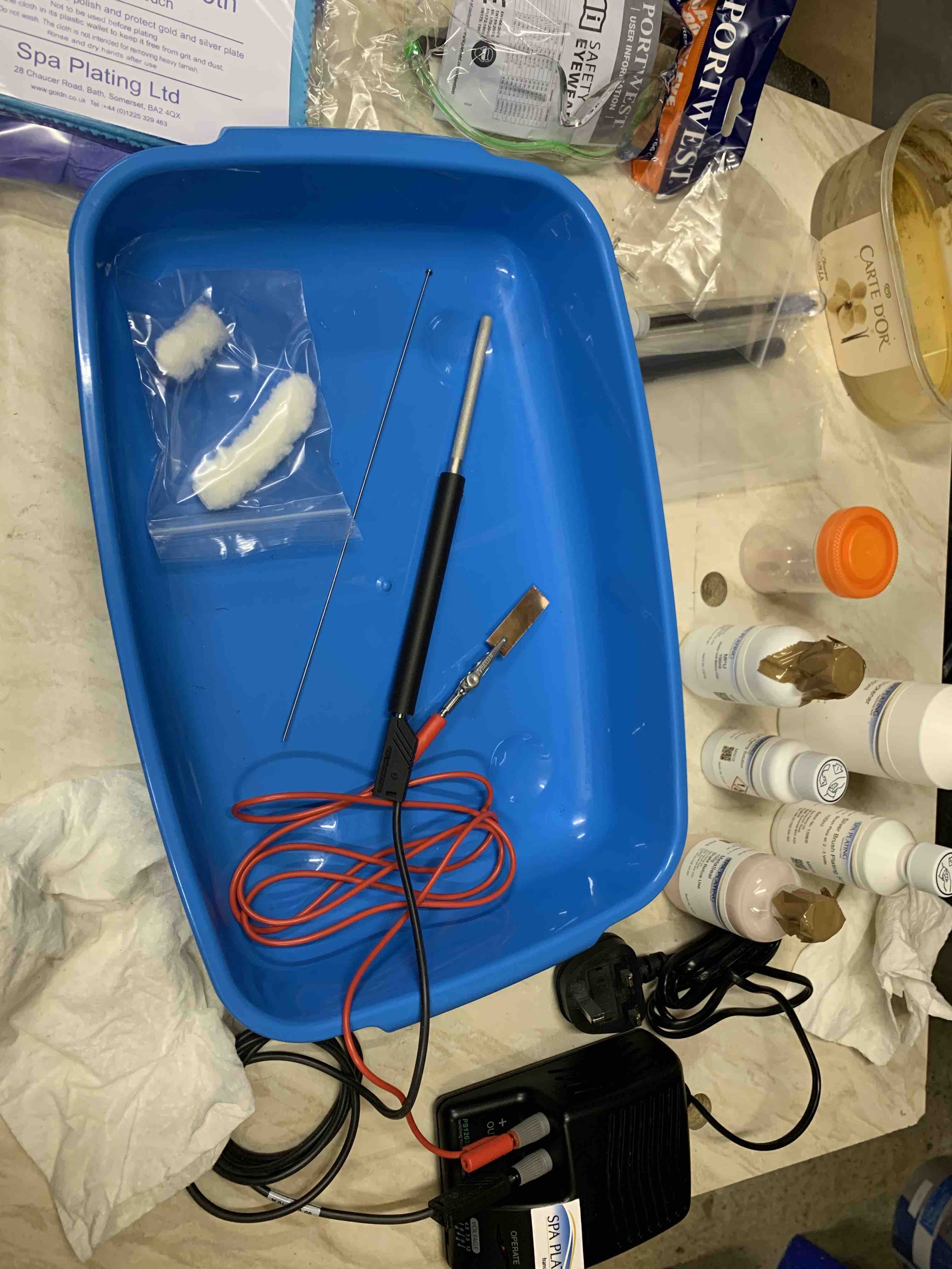
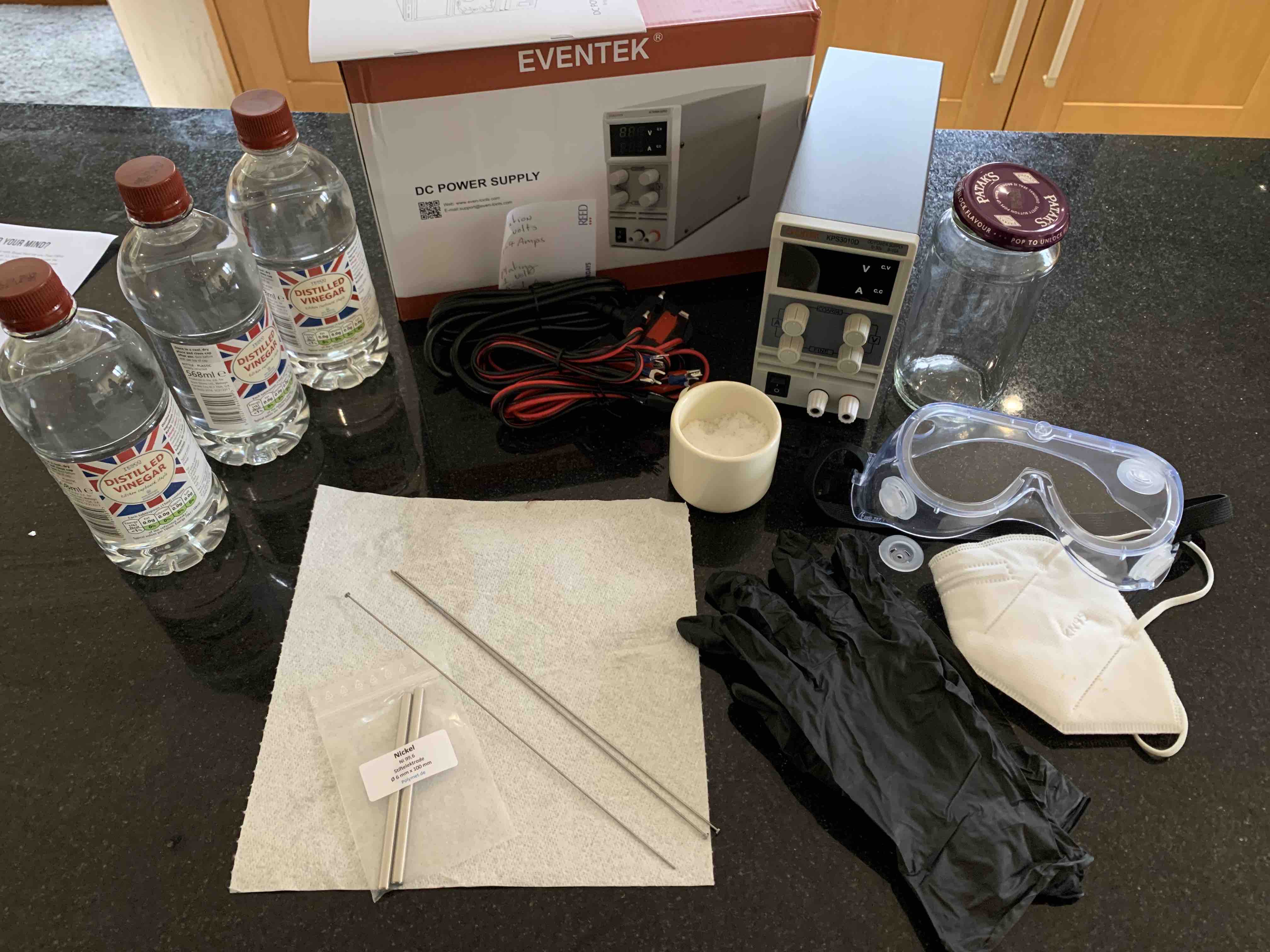 Again, it was my first time plating anything, so I bought some equipment.
First I need to actually make some nickel plating solution
Again, it was my first time plating anything, so I bought some equipment.
First I need to actually make some nickel plating solution
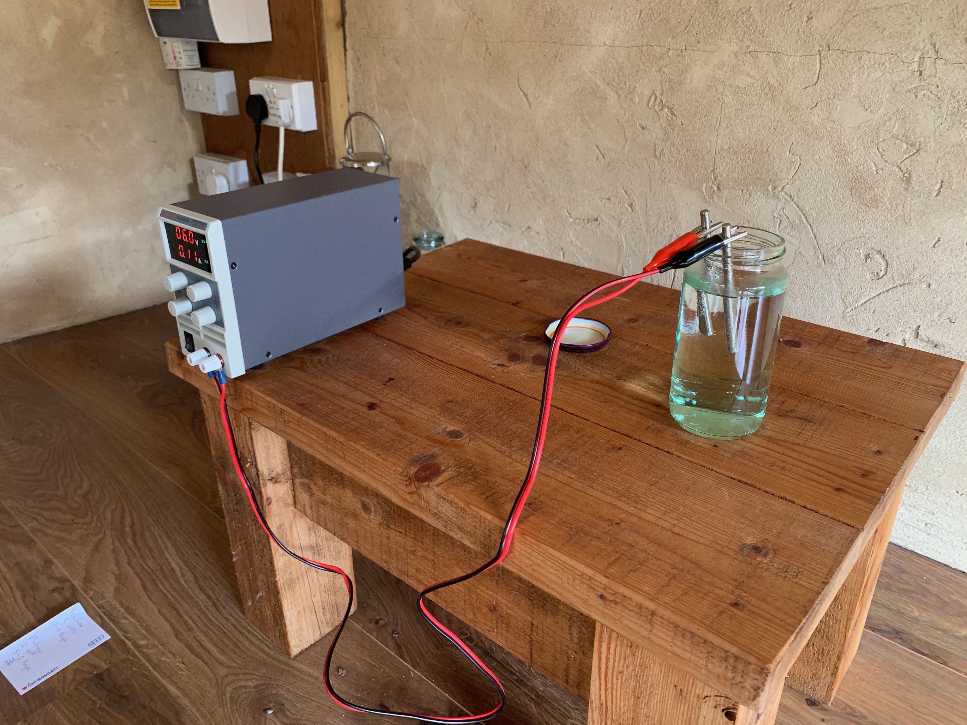
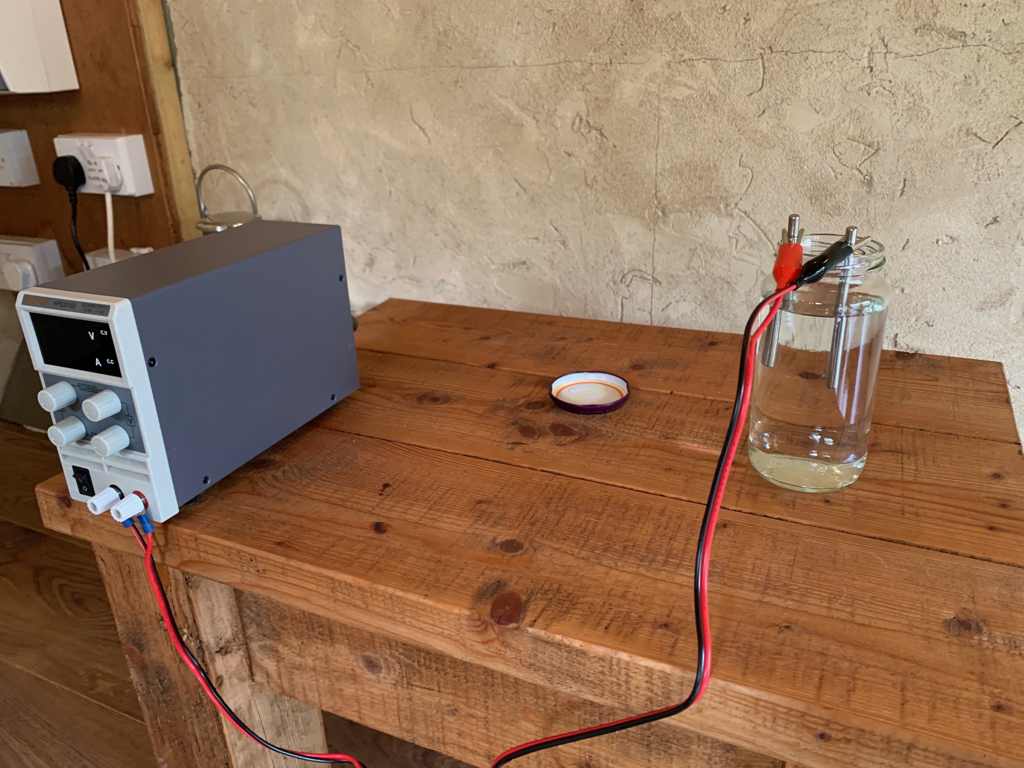 My simple setup, two nickel rods in a glass full of vinegar, connected to
a power supply
My simple setup, two nickel rods in a glass full of vinegar, connected to
a power supply
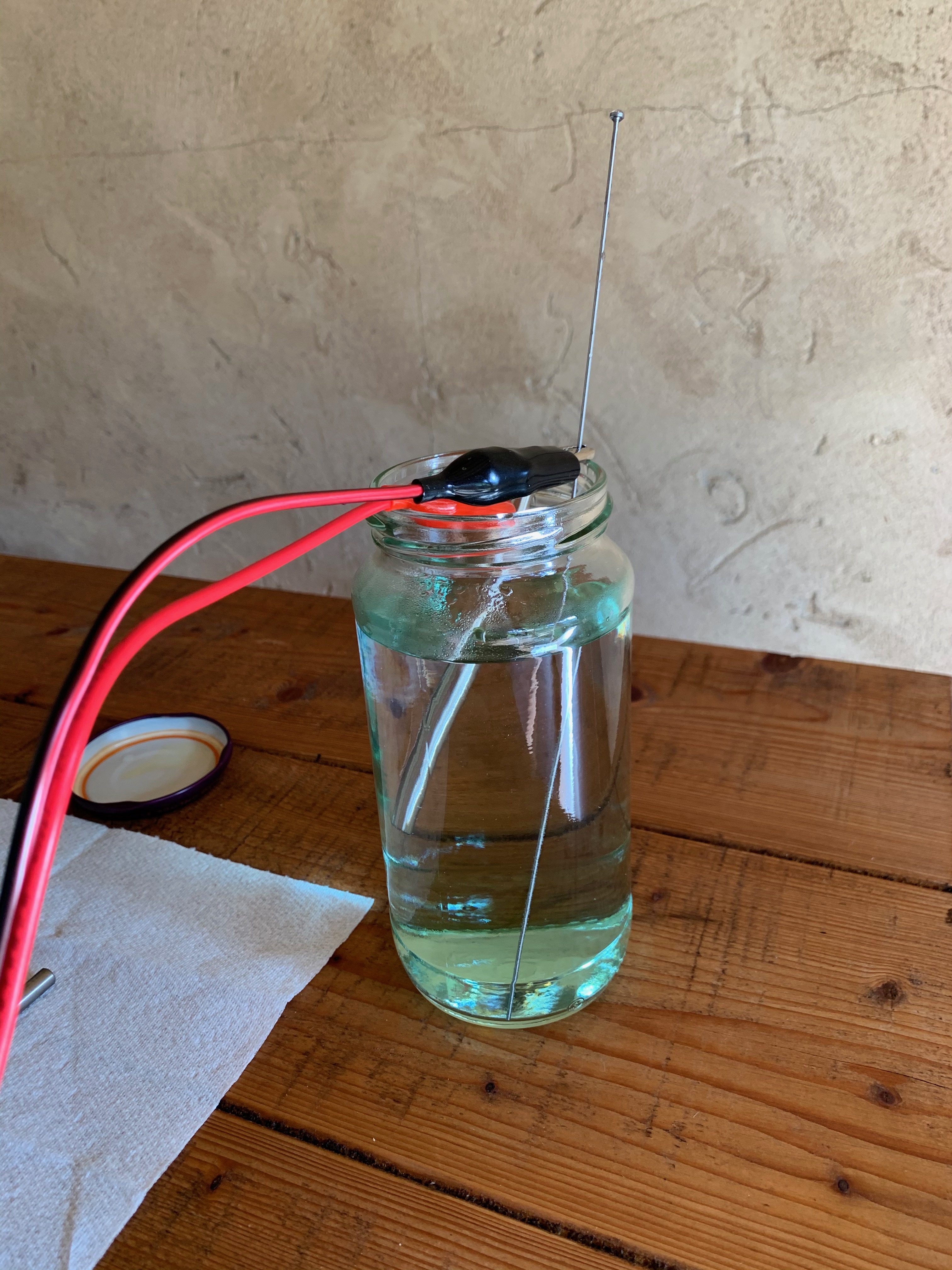
 After about an hour or so, the liquid starts to turn green, a tell-tale sign
that it's working.
After about an hour or so, the liquid starts to turn green, a tell-tale sign
that it's working.
 My first attempt at nickel plating, how wrong was I? fail.
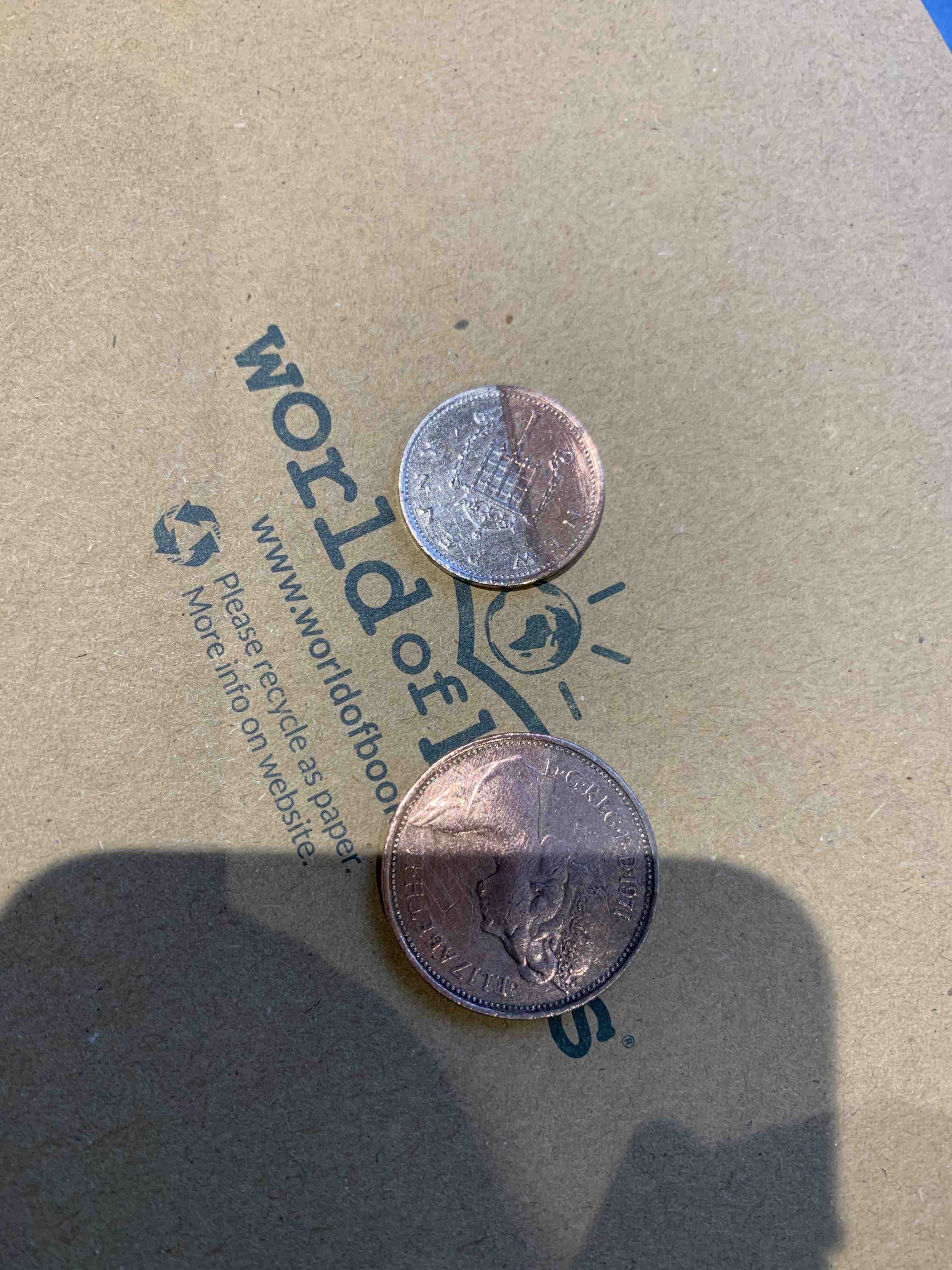
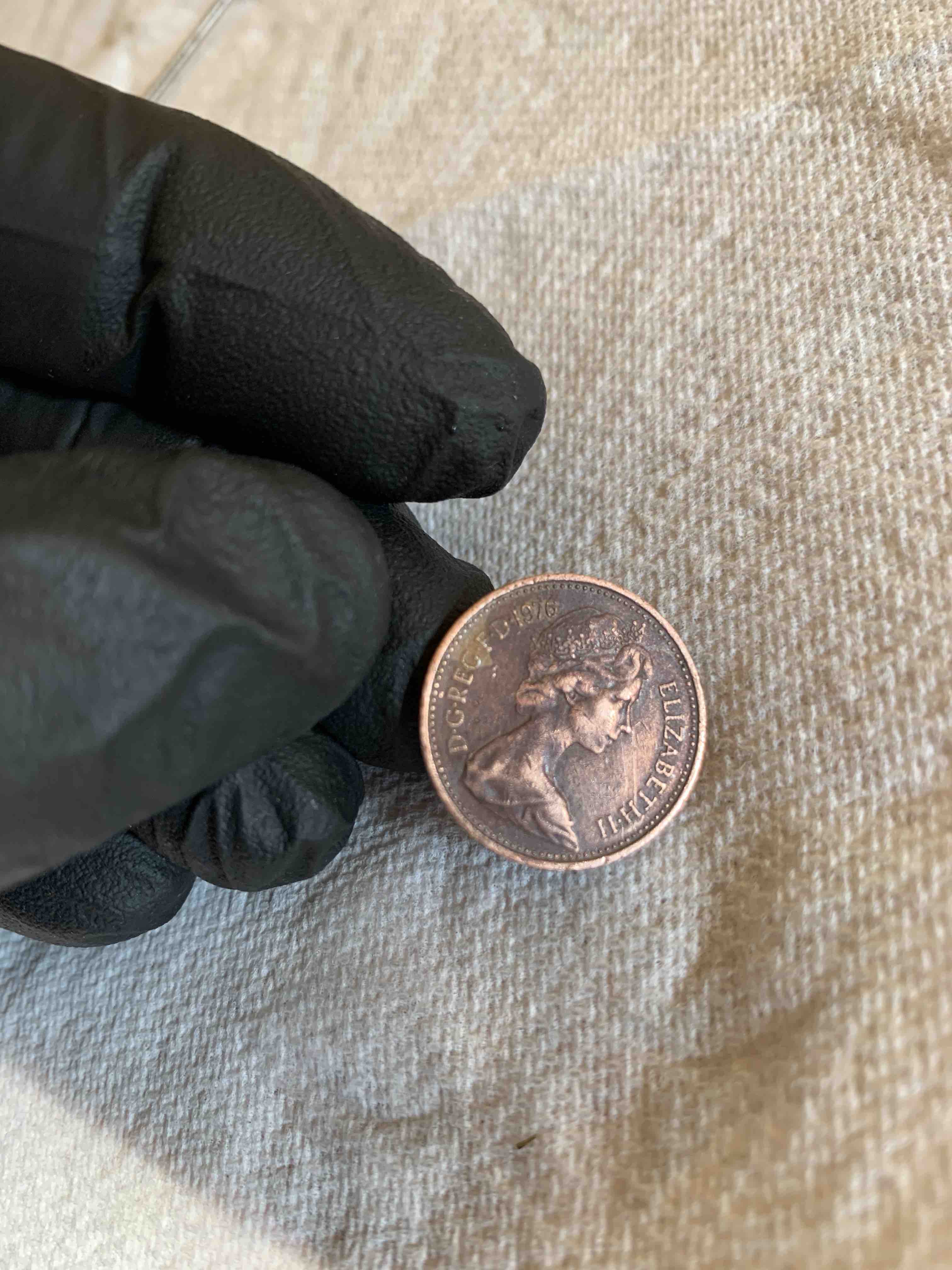 I tried to nickel plate a penny, whilst it looks silver~ish, it wasn't what
I was expecting...failed.
Note: I was testing on a penny because it's quite difficult to see on the
already silver rod if it was getting more silver
I tried to nickel plate a penny, whilst it looks silver~ish, it wasn't what
I was expecting...failed.
Note: I was testing on a penny because it's quite difficult to see on the
already silver rod if it was getting more silver
 I was getting what looked like burn marks on the rod, was it left over oil?
Was it something else?
I was getting what looked like burn marks on the rod, was it left over oil?
Was it something else?
 After some experimenting with voltages my penny seemed to look better
 I start to make notes of my tests, so far, all failures
 I ordered some fine-detail plastic versions of the grommet mold, they
were alot cheaper than the PA12.
I also ordered some rubber dye as the grommet should be black, not pink.
I ordered some fine-detail plastic versions of the grommet mold, they
were alot cheaper than the PA12.
I also ordered some rubber dye as the grommet should be black, not pink.
 This is quite hard to see, but the bottom part of the antenna has been plated,
the top part has some bad burns.
This is quite hard to see, but the bottom part of the antenna has been plated,
the top part has some bad burns.
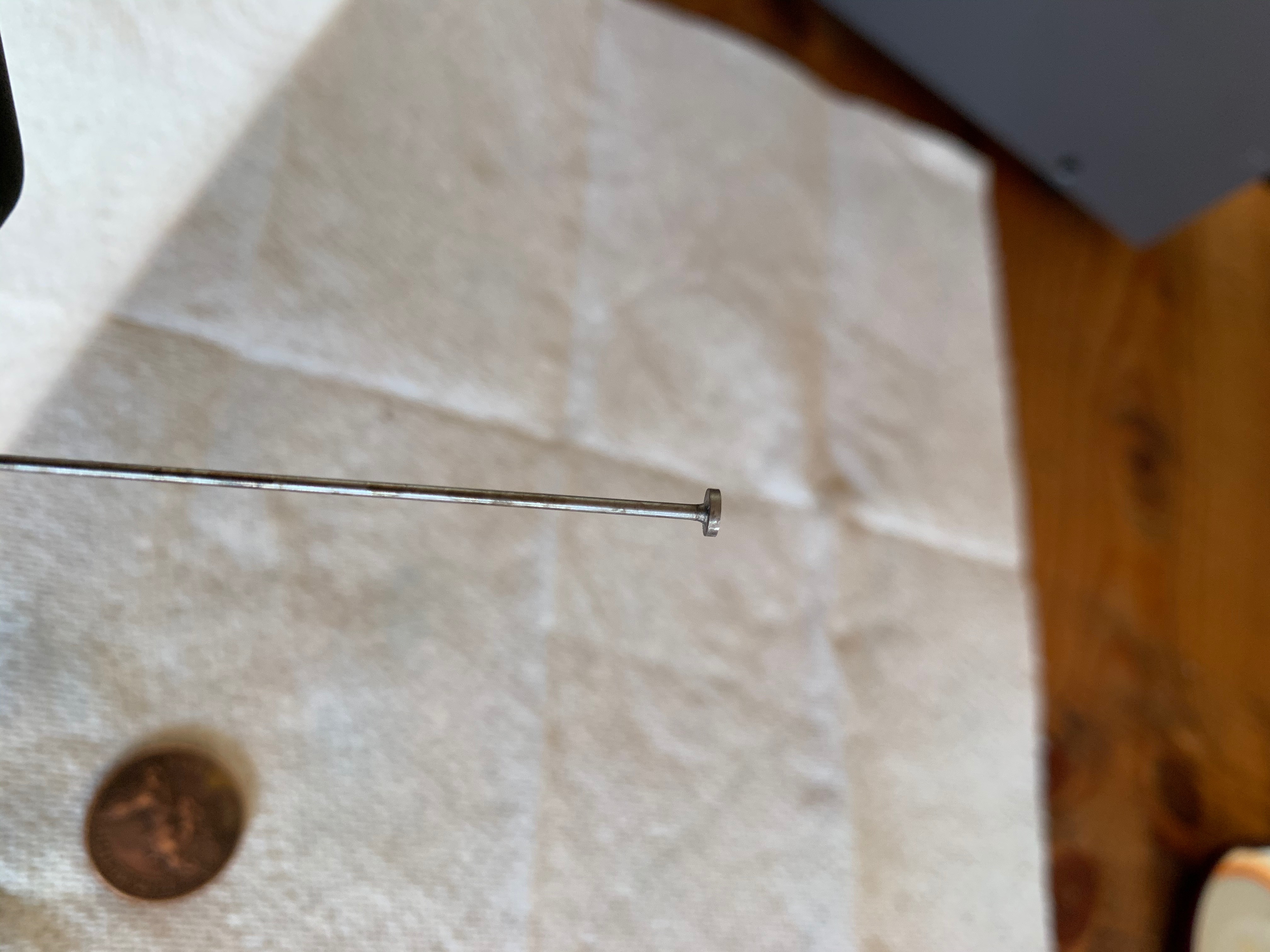
 A reminder that these antennas are delicate
 Here's a better picture of one of the ends plated, but I could see I was
running into a problem. Whenever I plated one end, the other end would
get messed up, Was it the voltages? or did I just need a better setup.
I didn't snap a photo, but in the end, I created a larger bath for the antenna so that it
could be submerged as one piece.
Here's a better picture of one of the ends plated, but I could see I was
running into a problem. Whenever I plated one end, the other end would
get messed up, Was it the voltages? or did I just need a better setup.
I didn't snap a photo, but in the end, I created a larger bath for the antenna so that it
could be submerged as one piece.
 I kept on filling out my results
 Grommet molds ready to be opened
 Grommet mold results, the fine detail plastic are clear winners
 I was now a rank amateur in Nickel Plating, but I still needed to gold plate
the antenna, I had to buy a gold plating kit
I was now a rank amateur in Nickel Plating, but I still needed to gold plate
the antenna, I had to buy a gold plating kit
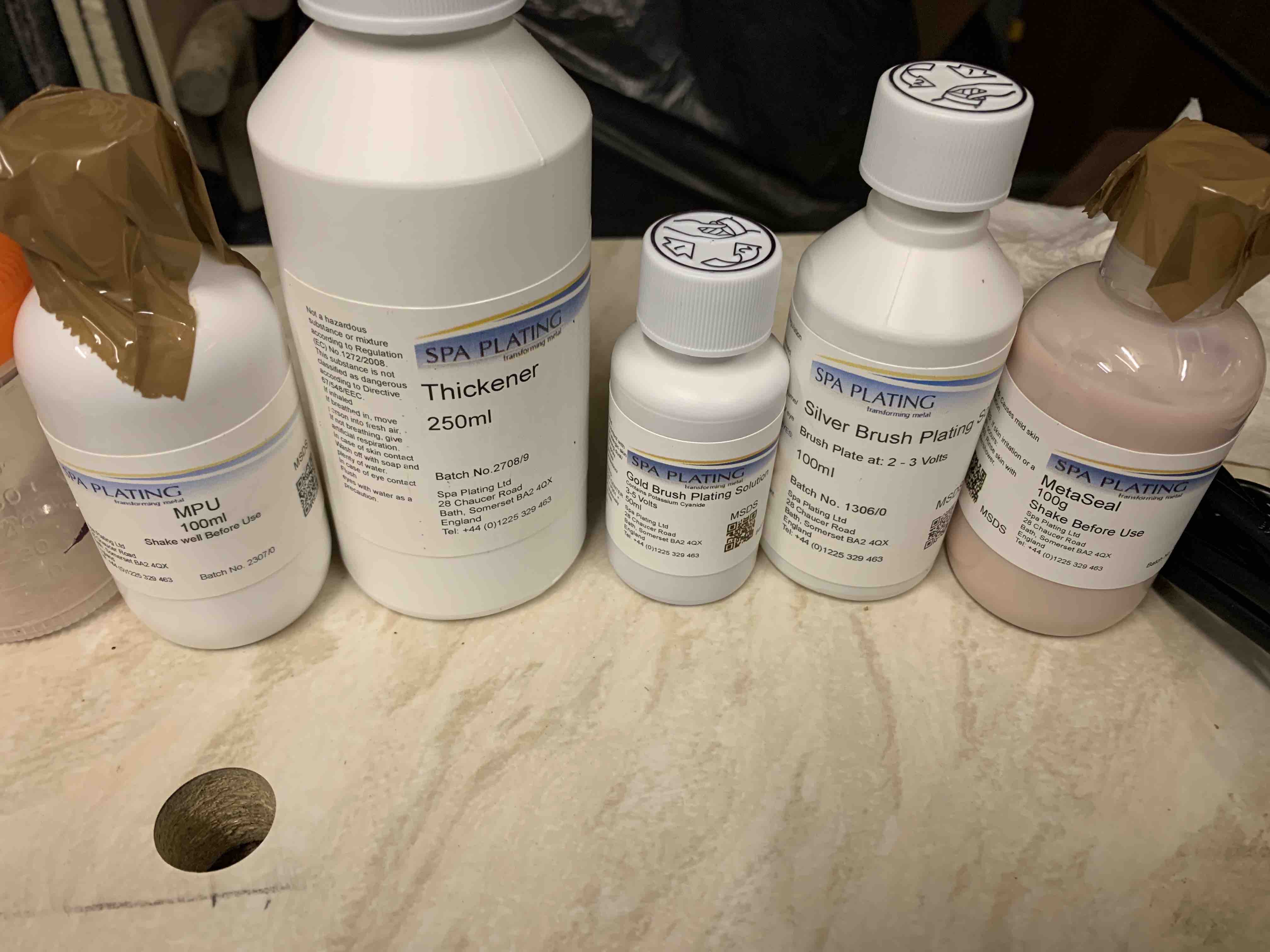 A collection of different gold plating chemicals
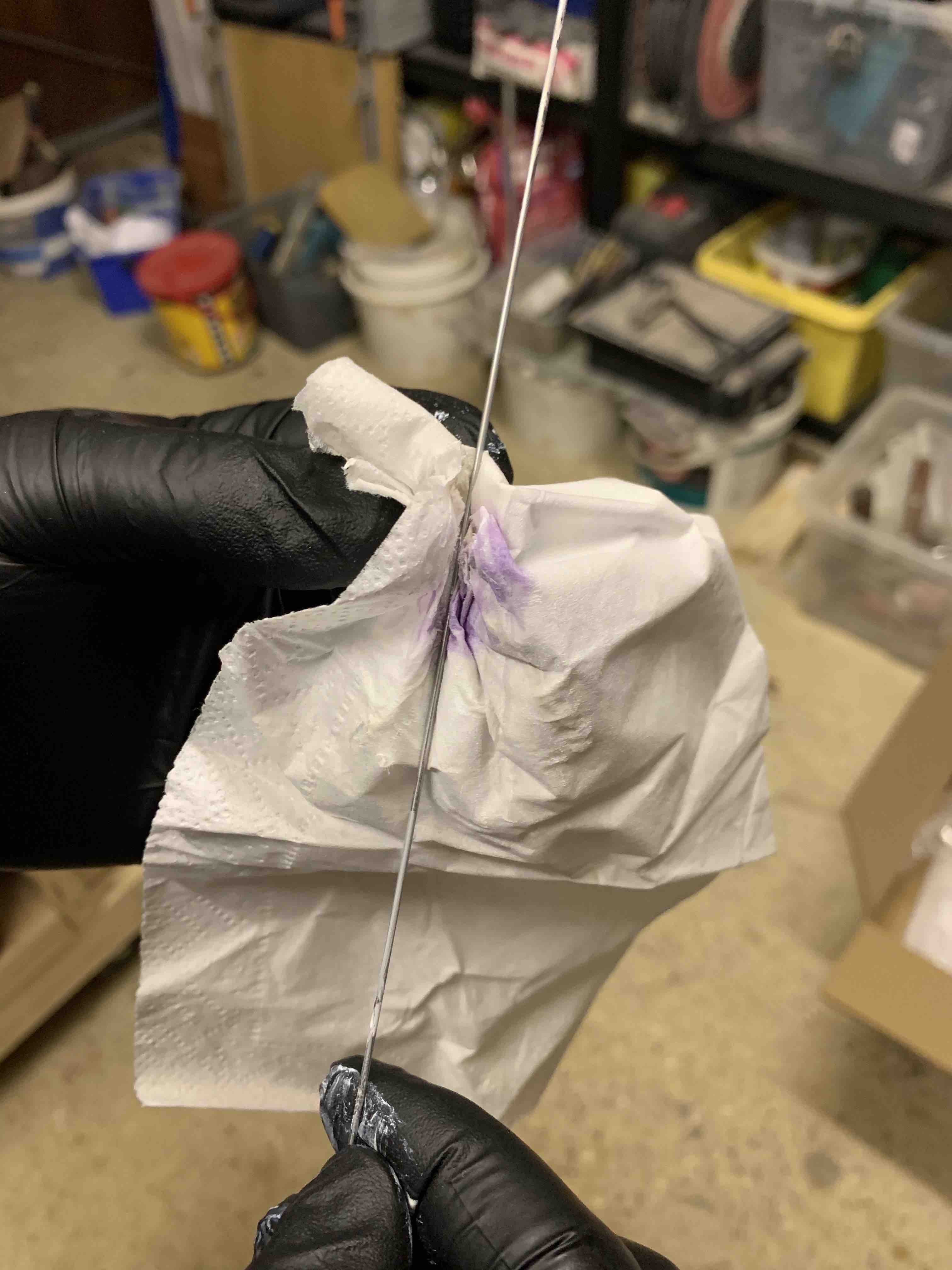 Preparing the antenna, it's worth mentioning my first attempts
failed badly, everything was burning...then I realised I had the poles
switched on the current
Preparing the antenna, it's worth mentioning my first attempts
failed badly, everything was burning...then I realised I had the poles
switched on the current
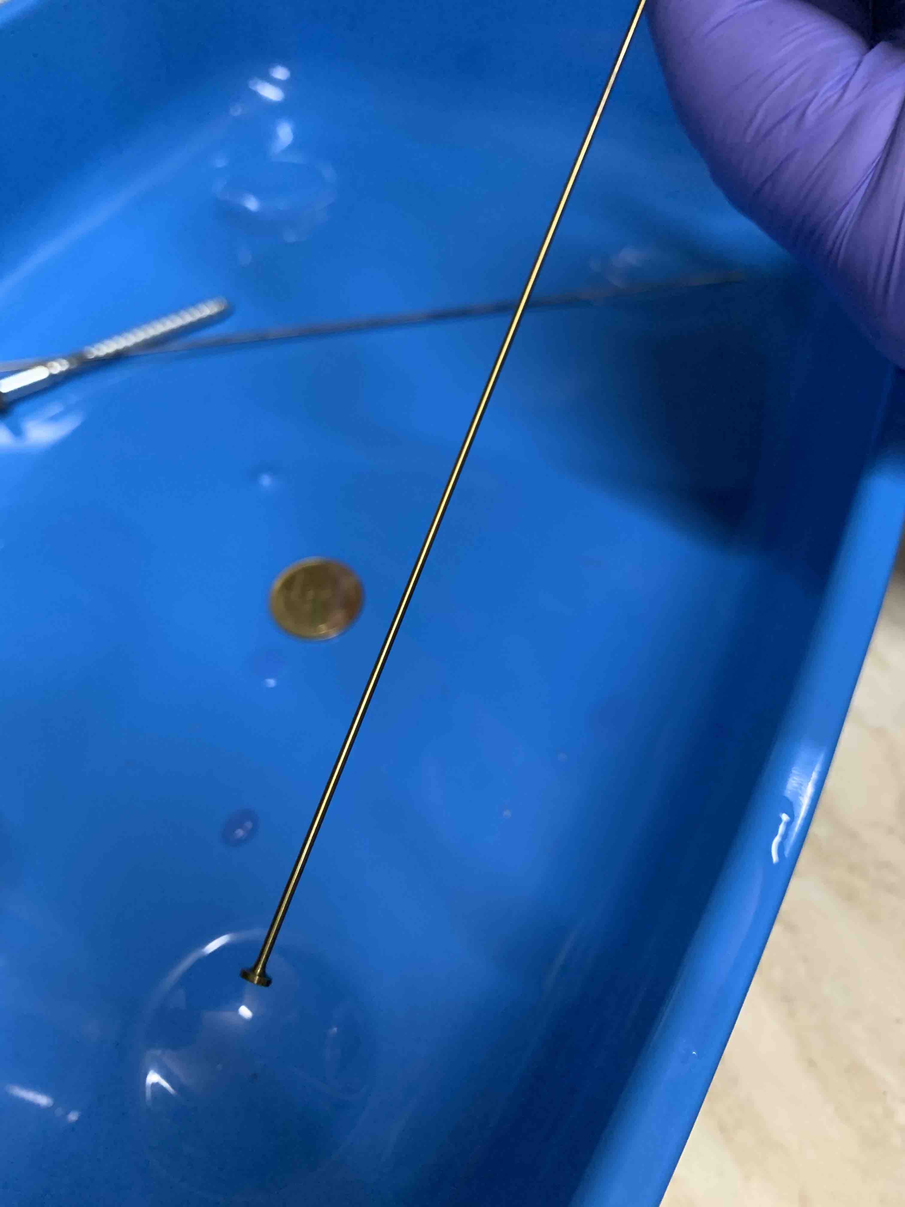 GOLD!
GOLD!
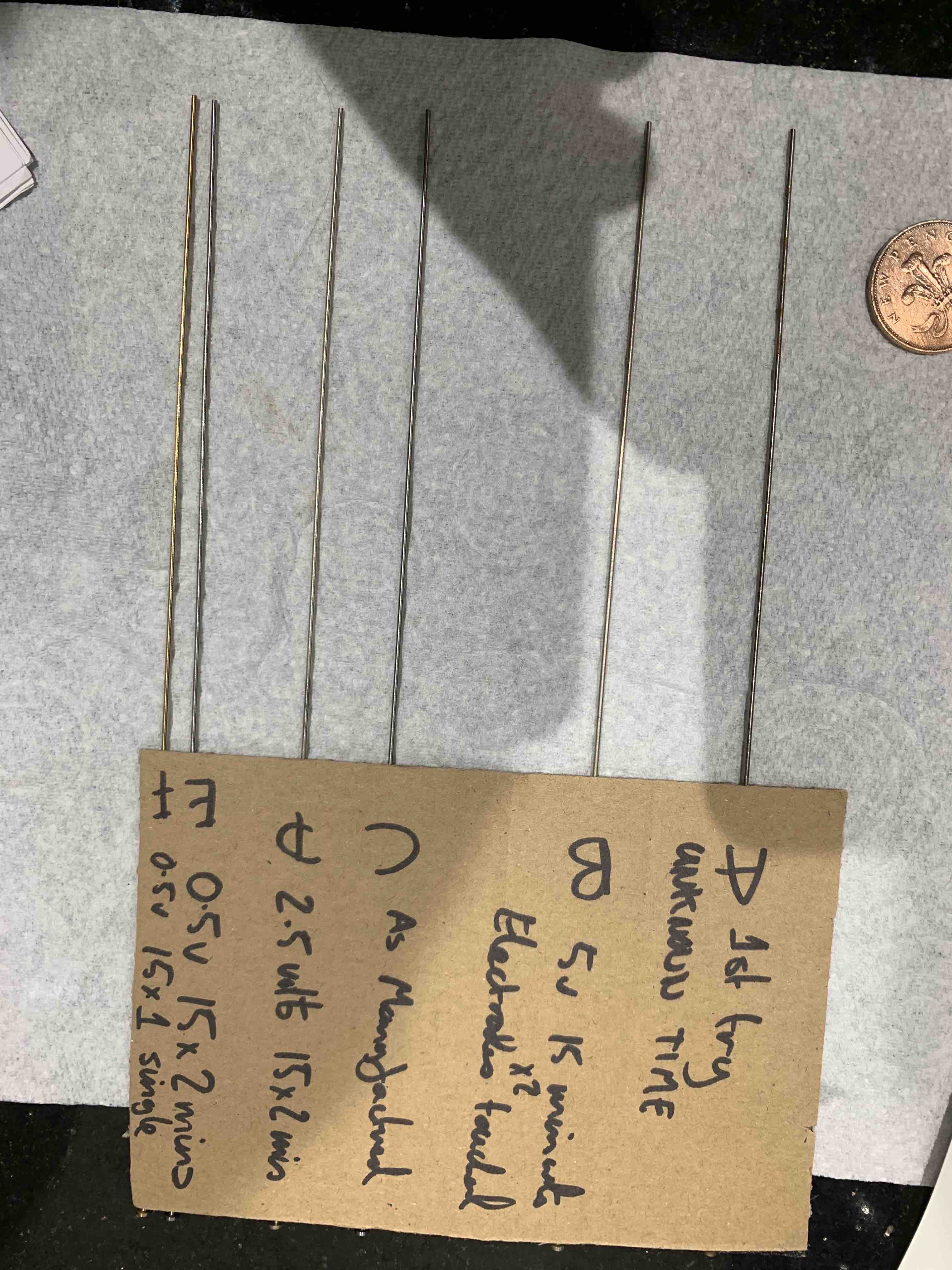 Compared to me table of results
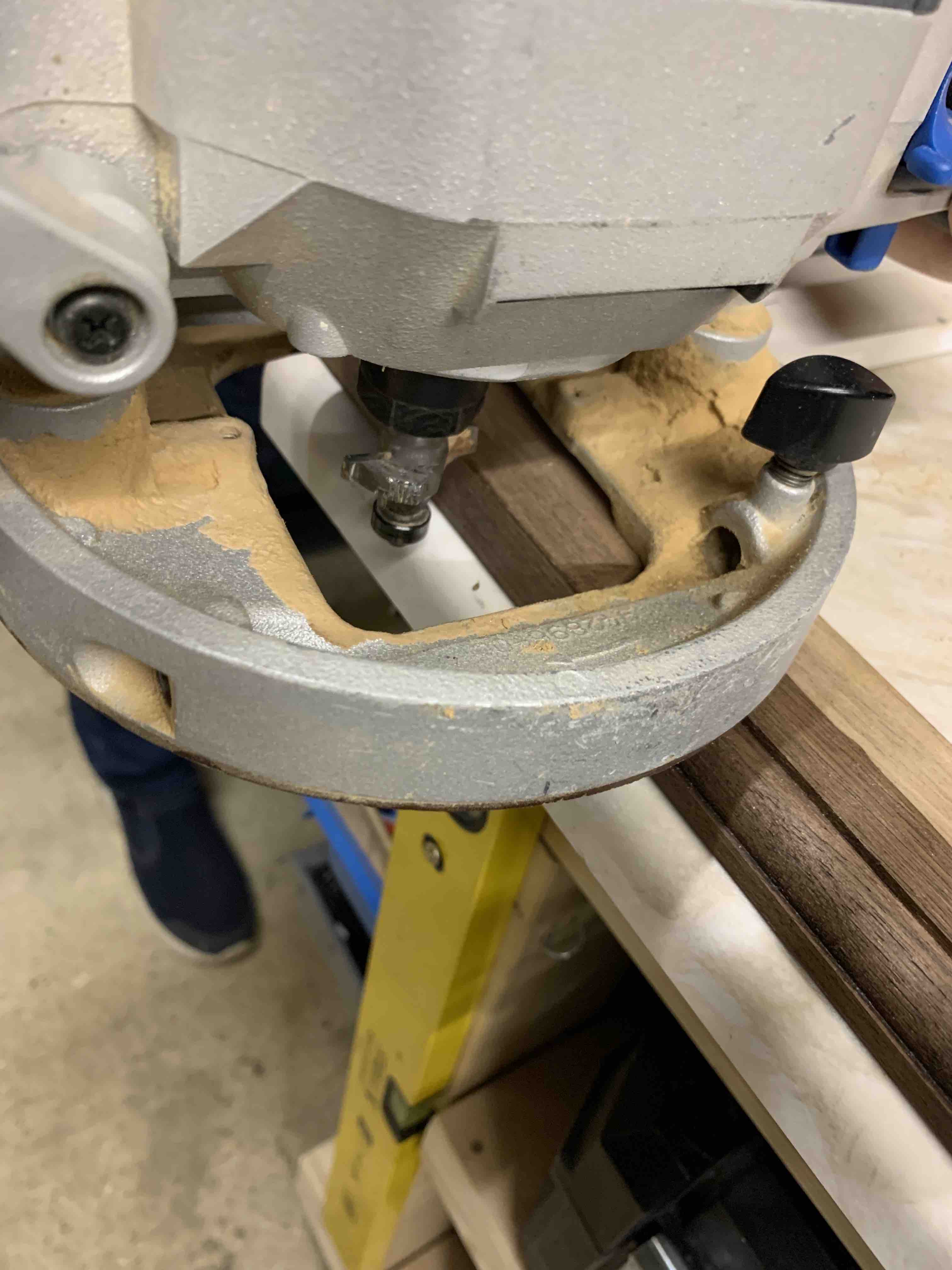 Routing the edge of the walnut
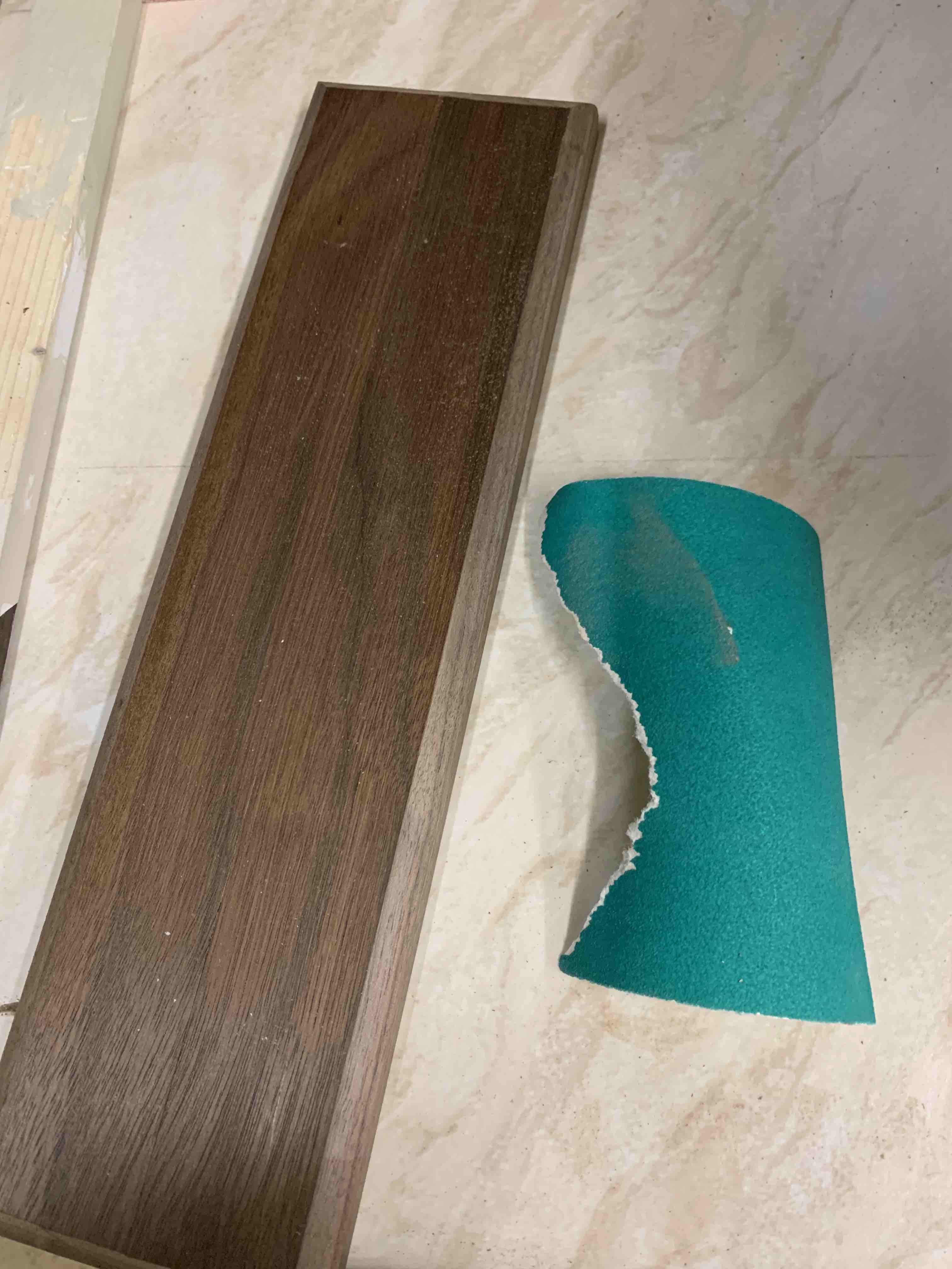 Once the routing was complete, it was time to sand down the edges
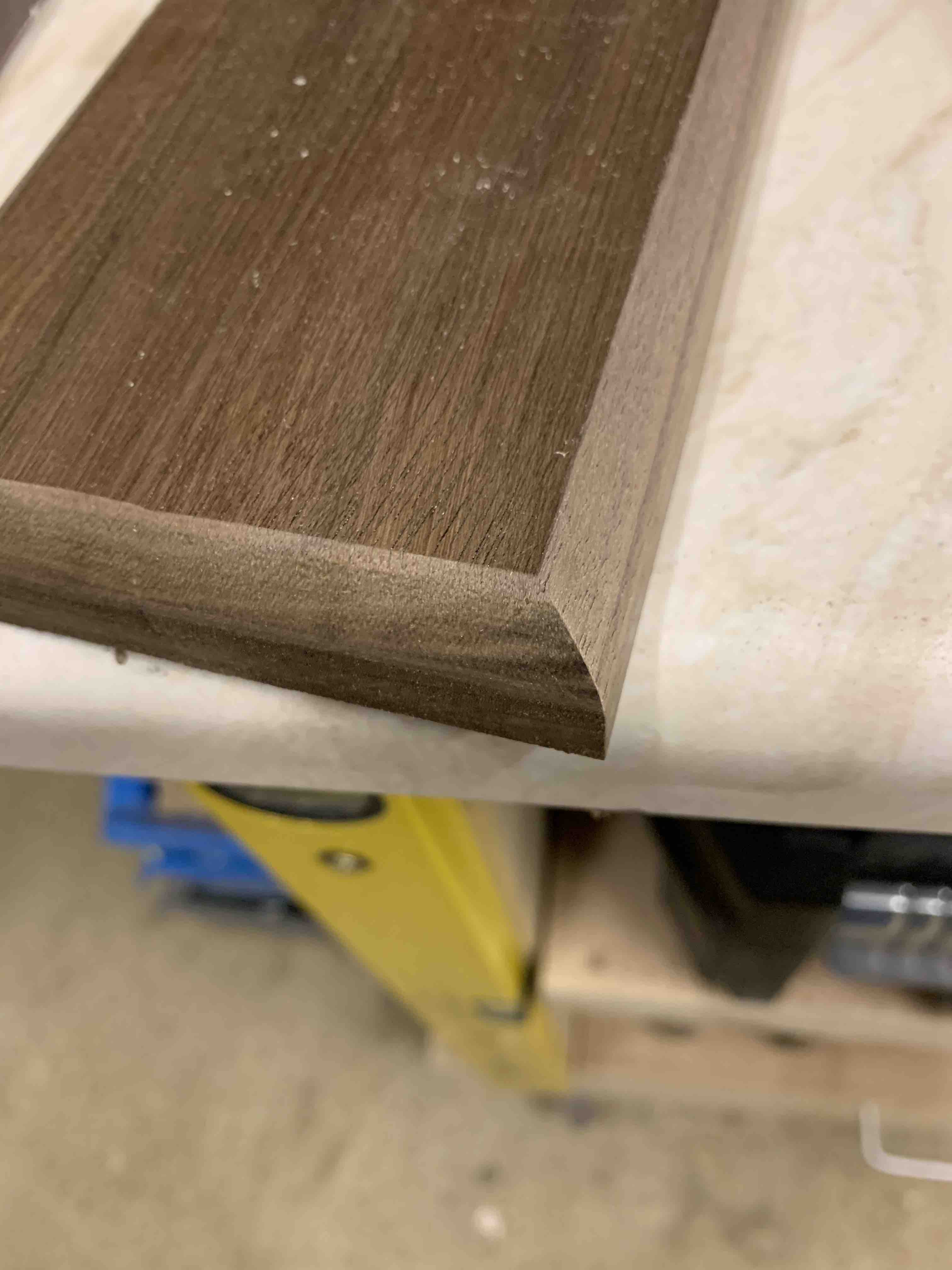 A closer look at the edge
 Getting prepared for assembly...but wait, the woods not done
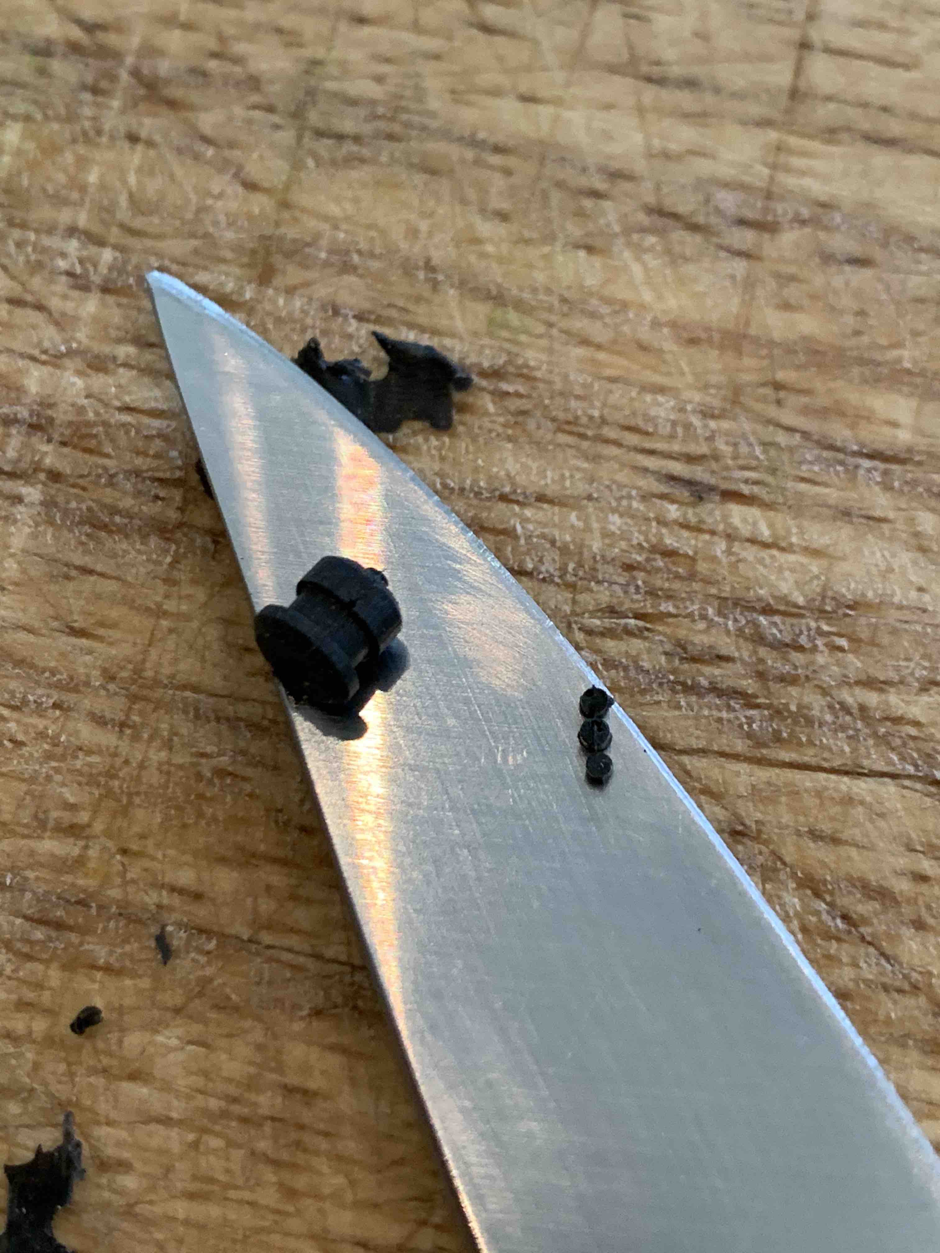 Removing the flashing from a grommet with a sharp knife
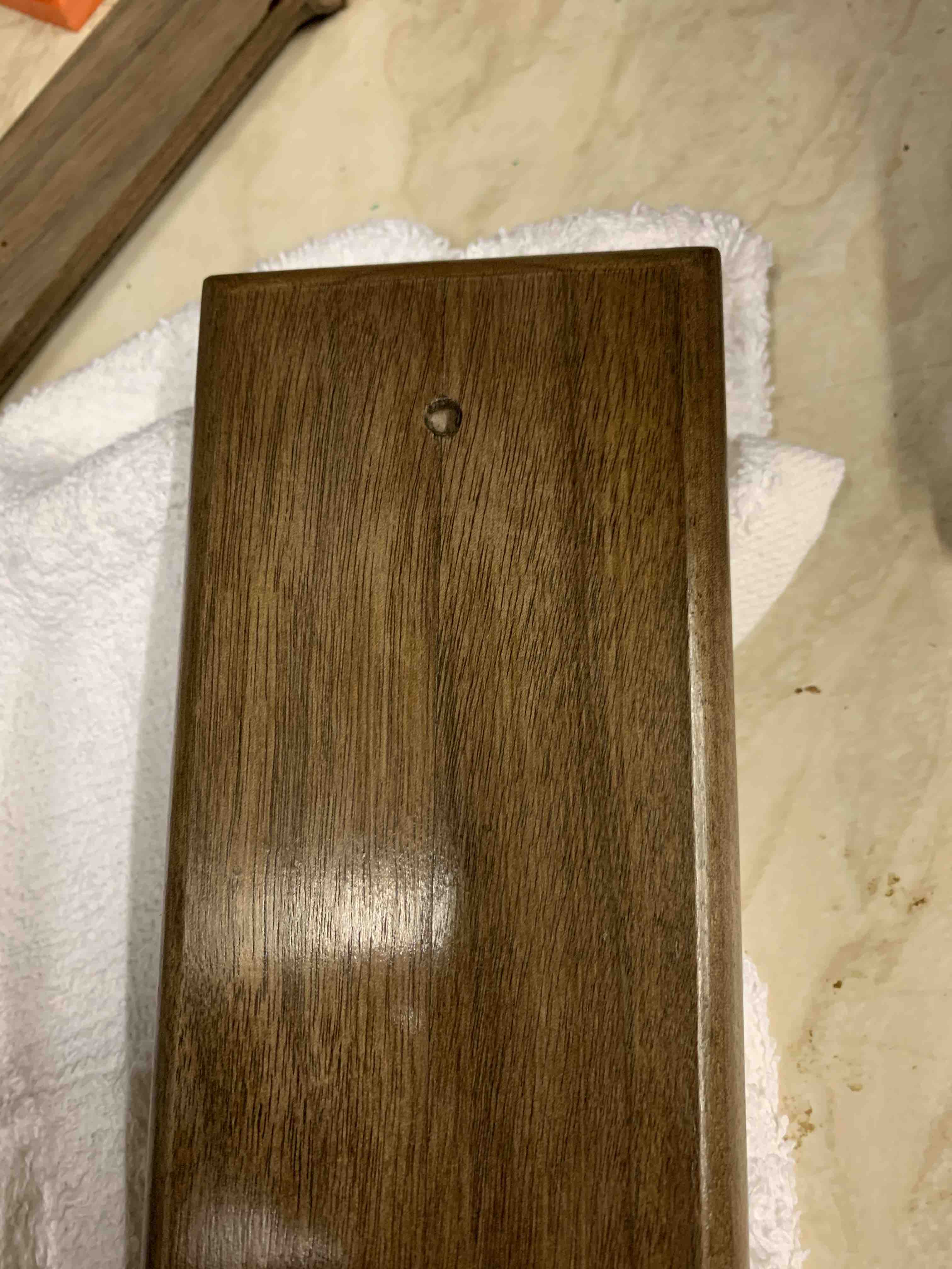
 Lining up the elements, the hole is for a magnet, I wanted to be able to take "The Thing"
off the plinth and disassemble it to show to people whenever I wanted.
Lining up the elements, the hole is for a magnet, I wanted to be able to take "The Thing"
off the plinth and disassemble it to show to people whenever I wanted.
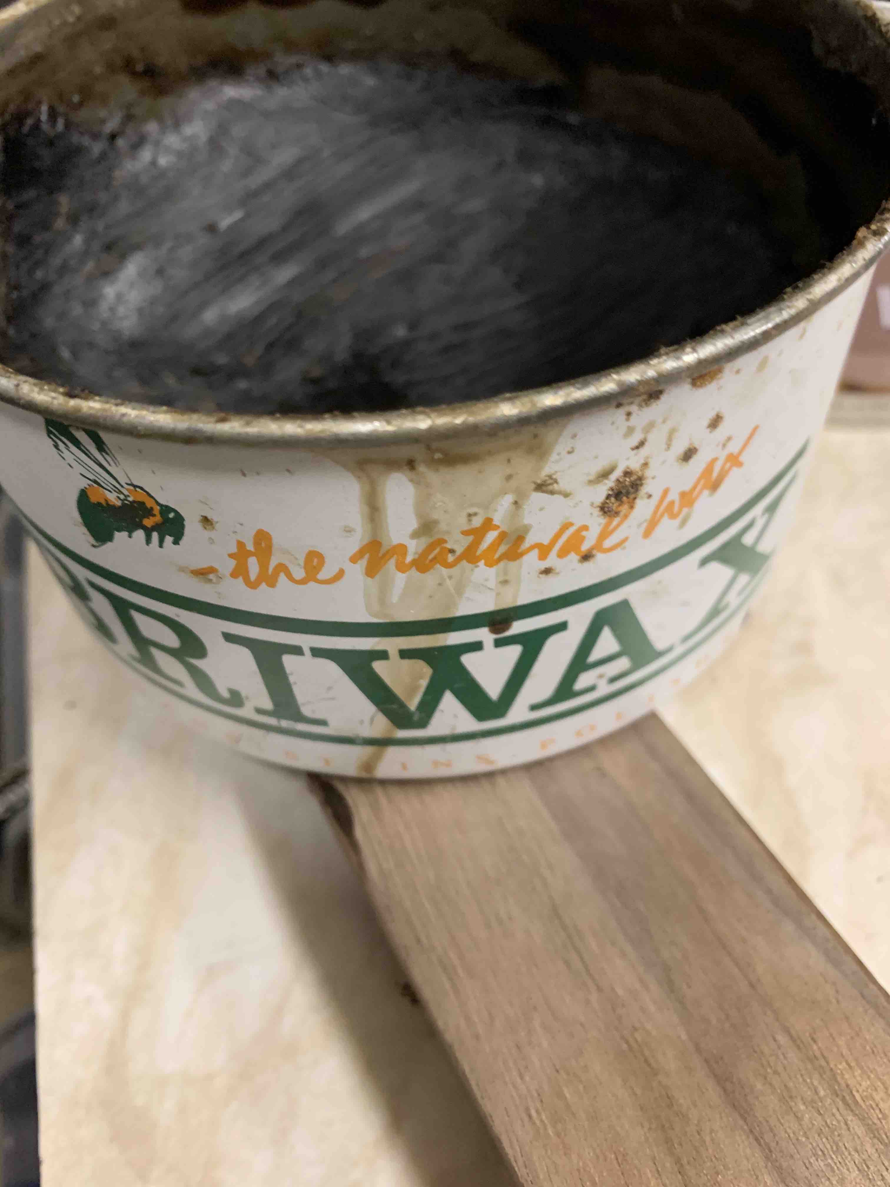 I wasn't happy with the varnish finish, and I was too impatient to wait for it to dry,
beeswax made the walnut amazing colour.
I wasn't happy with the varnish finish, and I was too impatient to wait for it to dry,
beeswax made the walnut amazing colour.
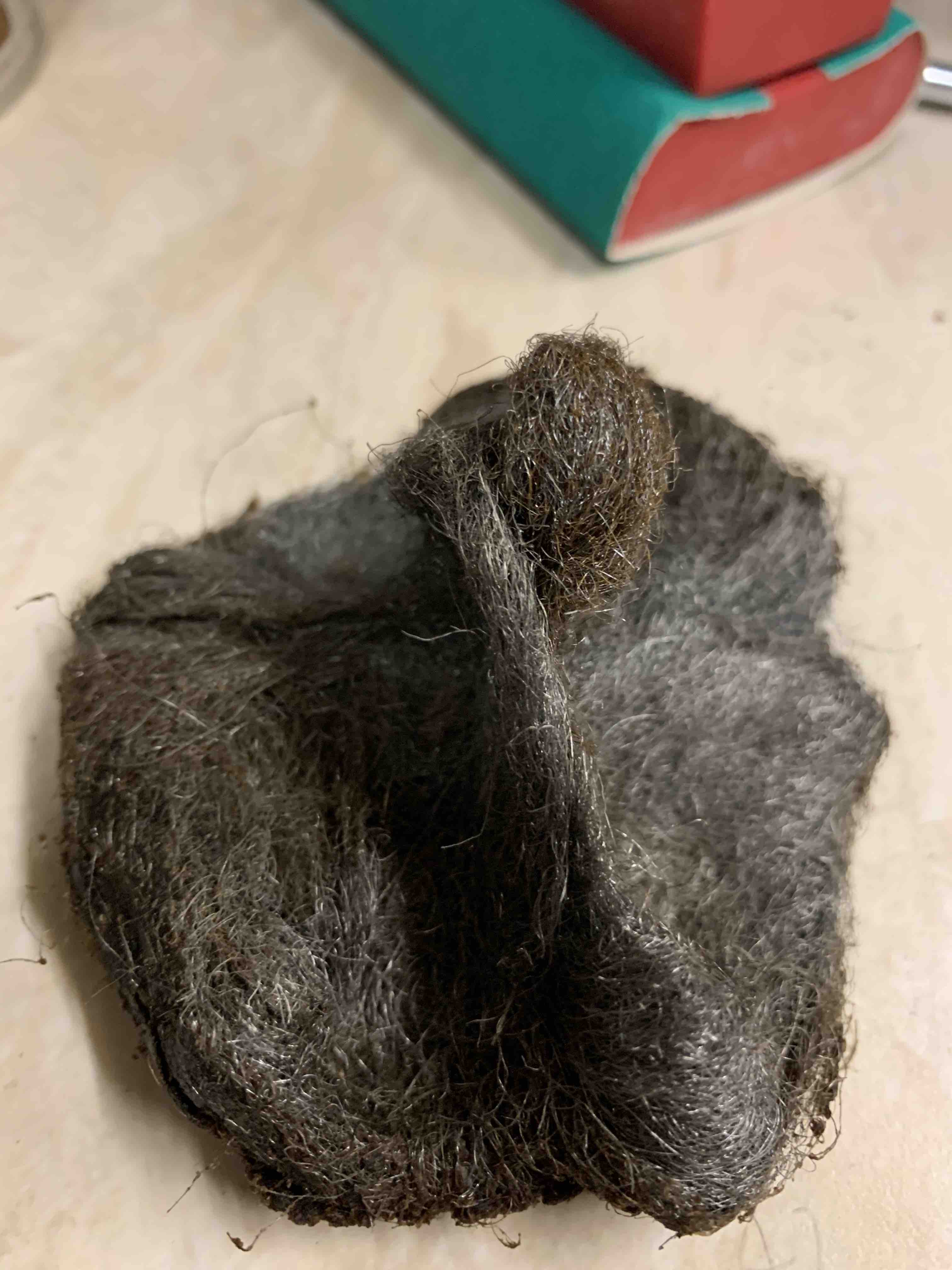 I didn't know, but applying the beeswax with wire wool works very well
 The walnut looks gorgeous with the bees wax
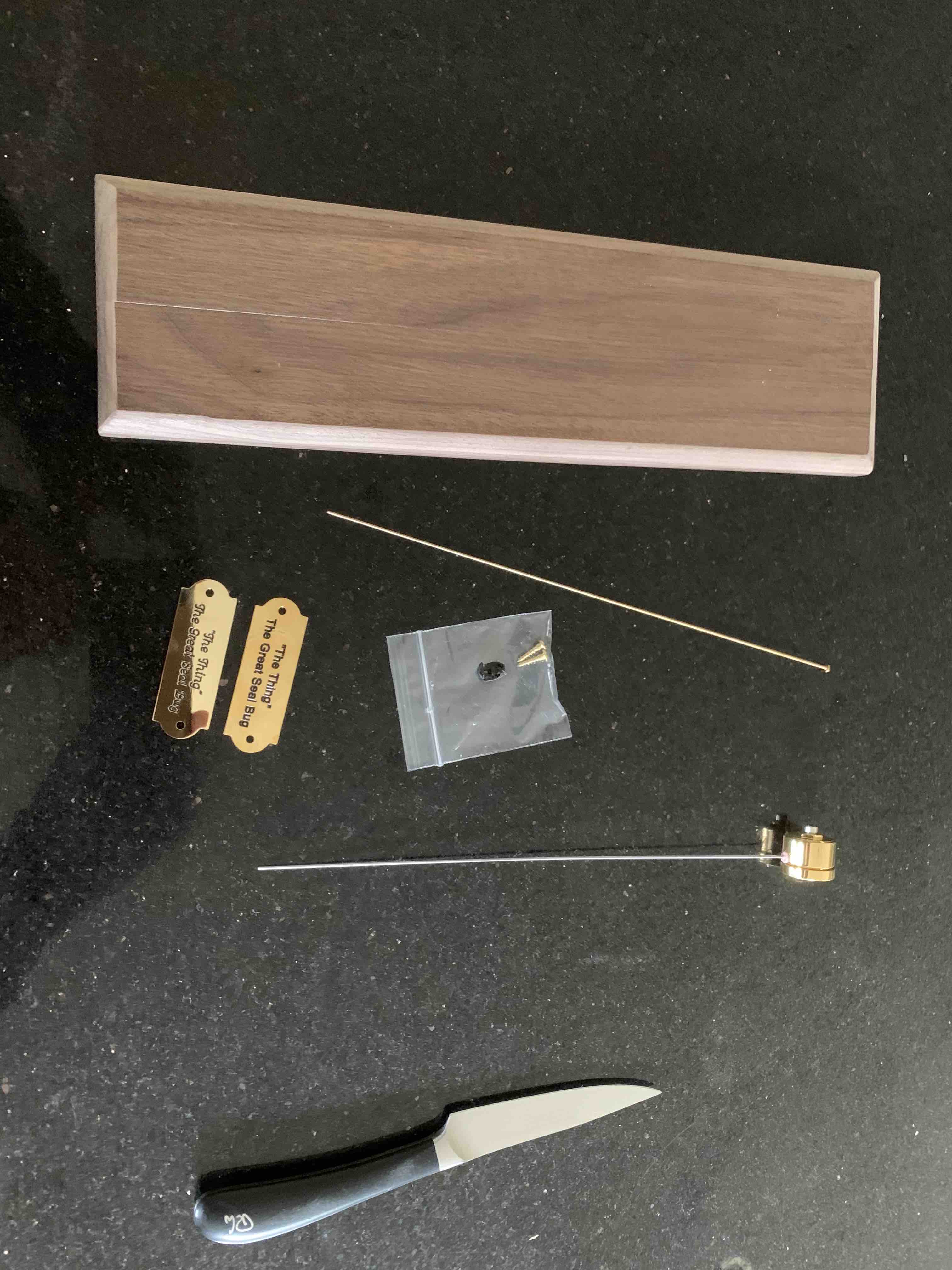
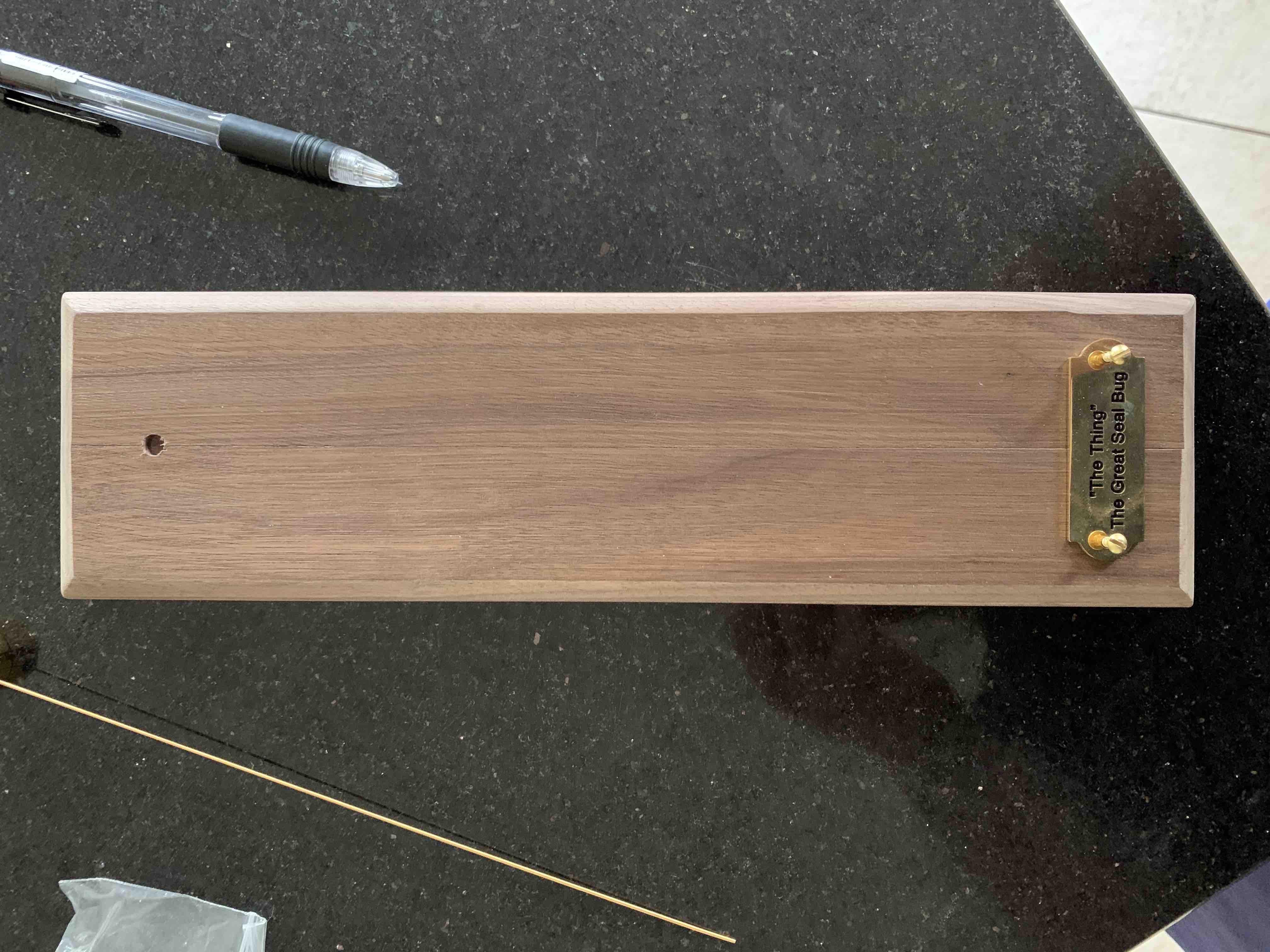
 Attaching the name plaque
 Glueing in the magnet and squeezing it in
 First full fix assembly photo
 Holding it against the wall to see how it looks
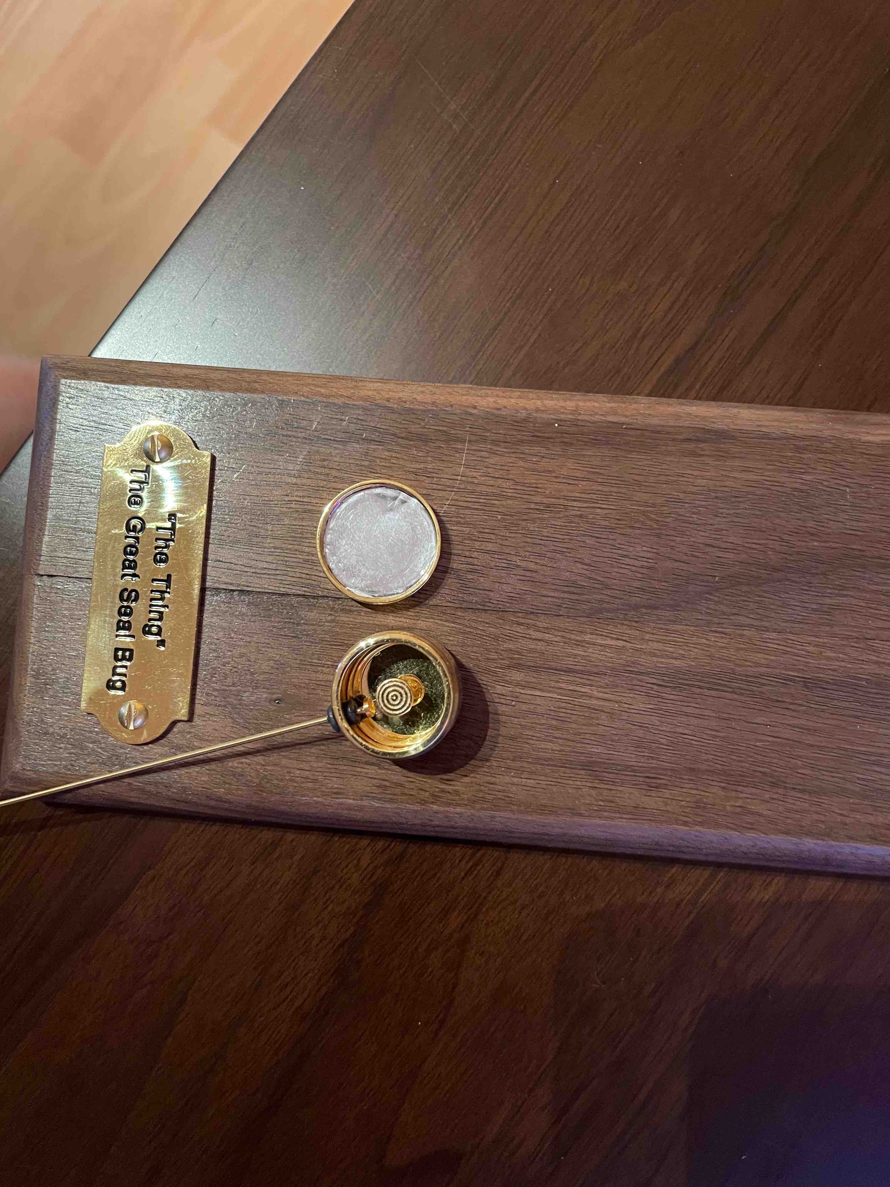
 Showing off the magnet attachment, I tried so many different magnets.
In the original design, the magnet was mounted behind the wood, but I couldn't
find a magnet strong enough at such small size
Showing off the magnet attachment, I tried so many different magnets.
In the original design, the magnet was mounted behind the wood, but I couldn't
find a magnet strong enough at such small size
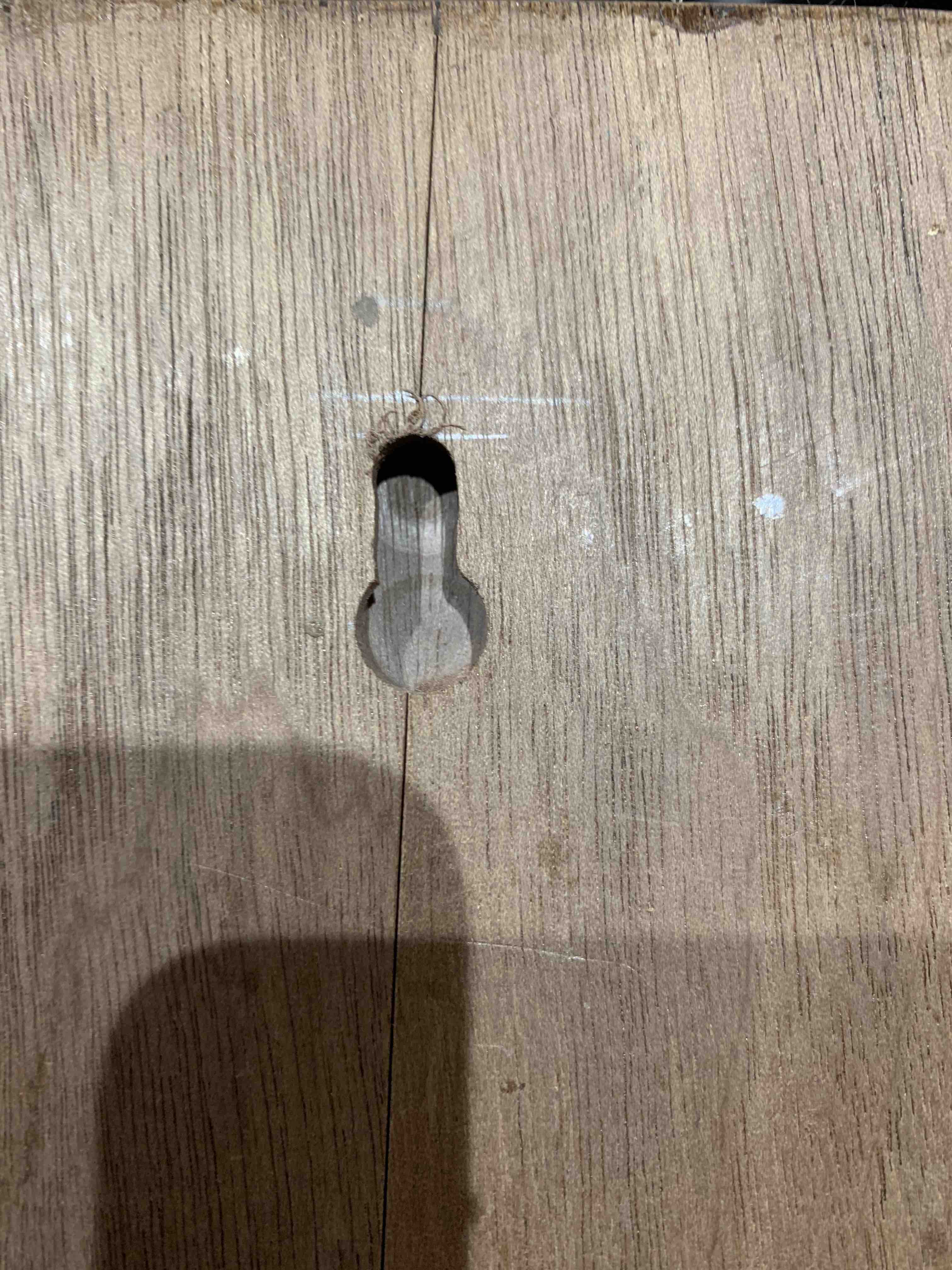 We purchased a special drill bit to drill an internal mounting hook into the
wood
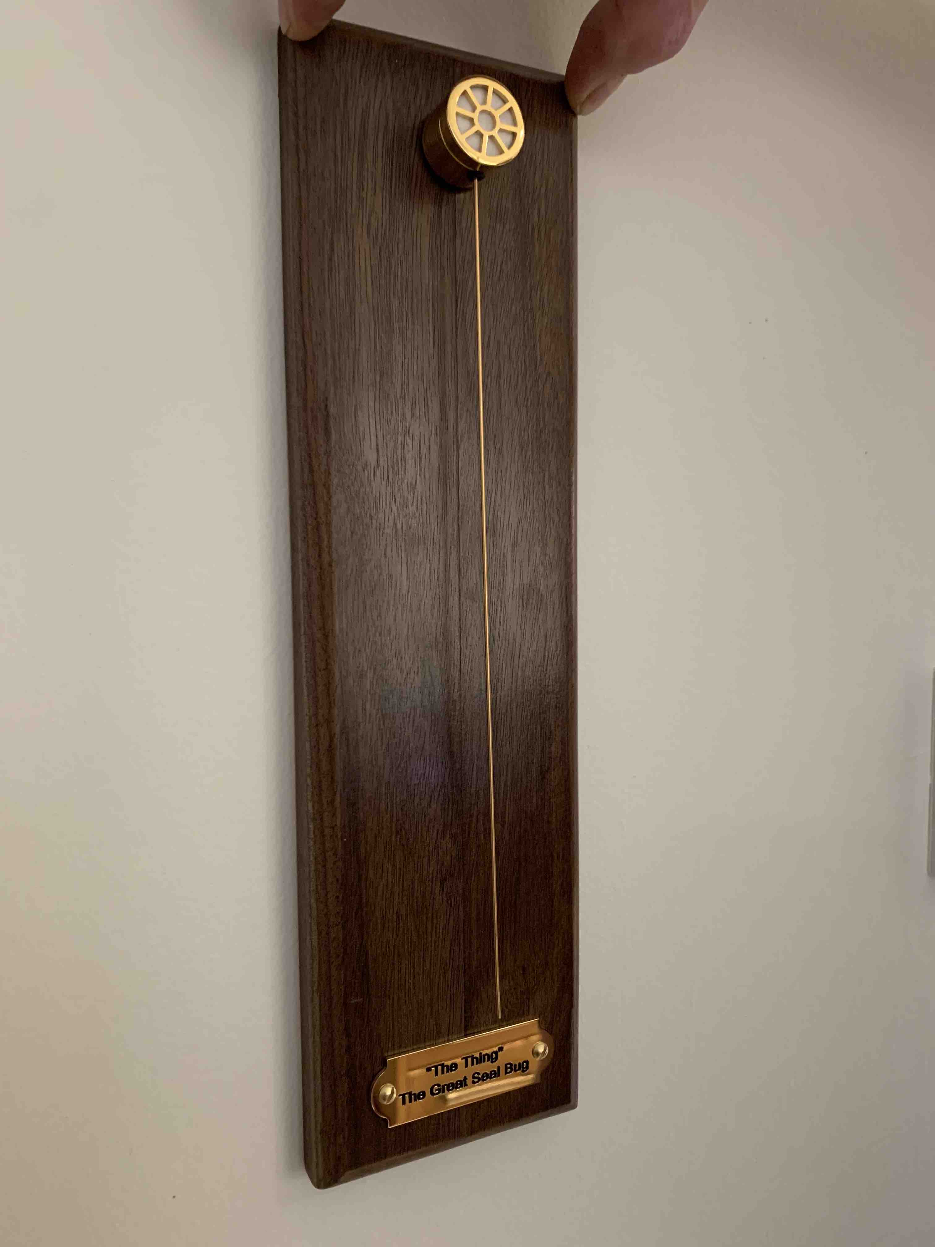
Proudly mounted on my wall
We purchased a special drill bit to drill an internal mounting hook into the
wood
Proudly mounted on my wall
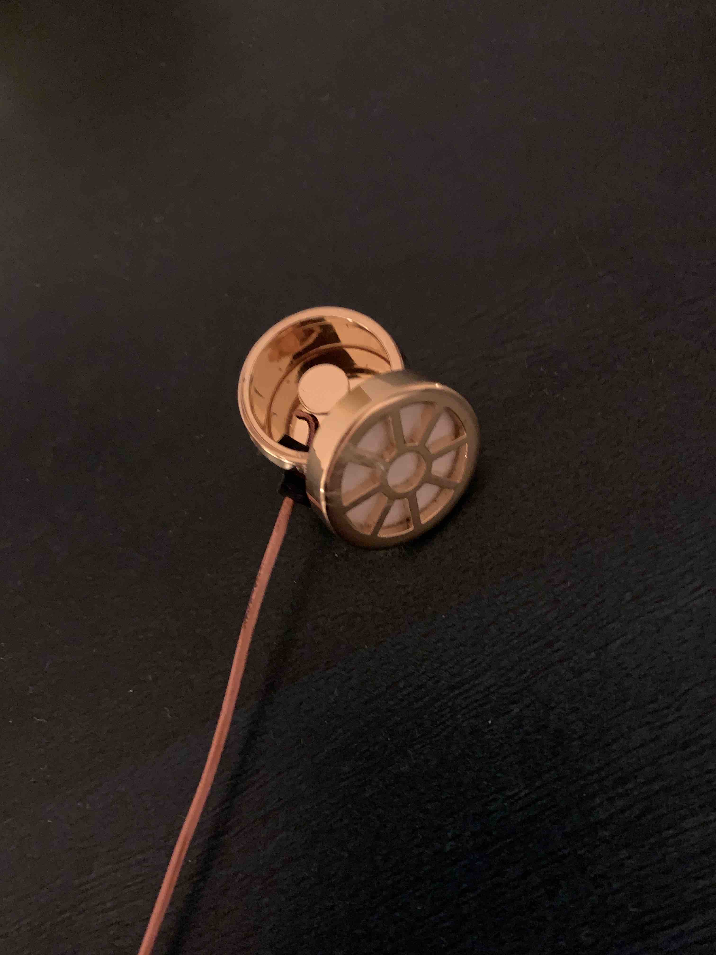
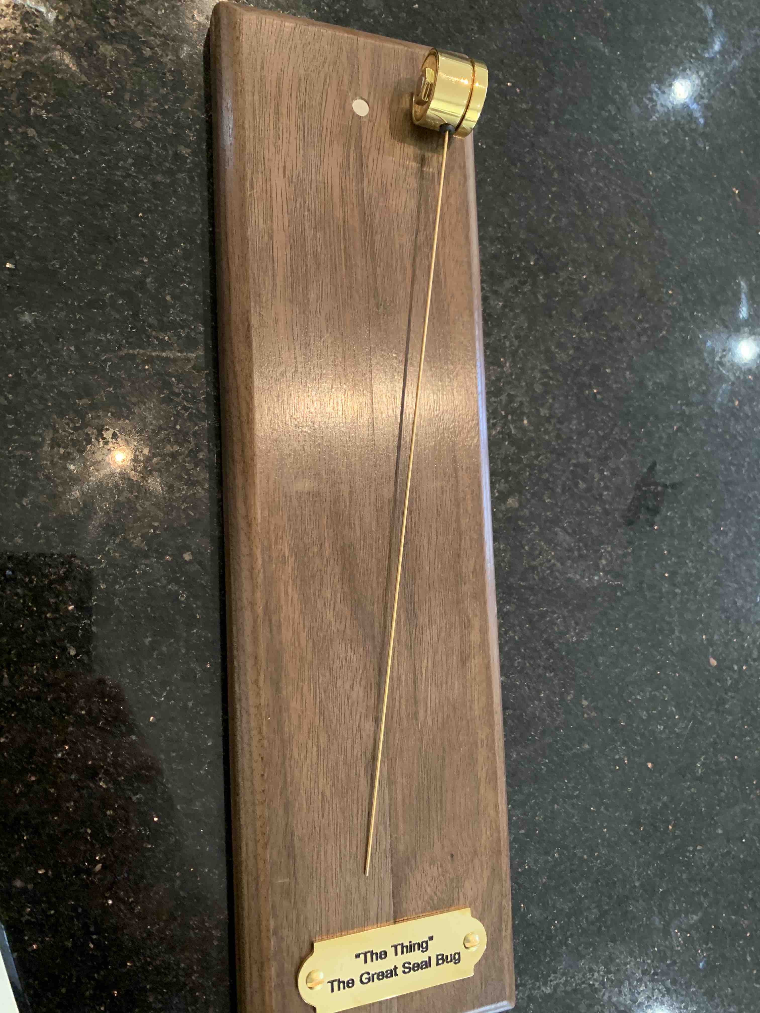
 Taken off the wall and showing the insides
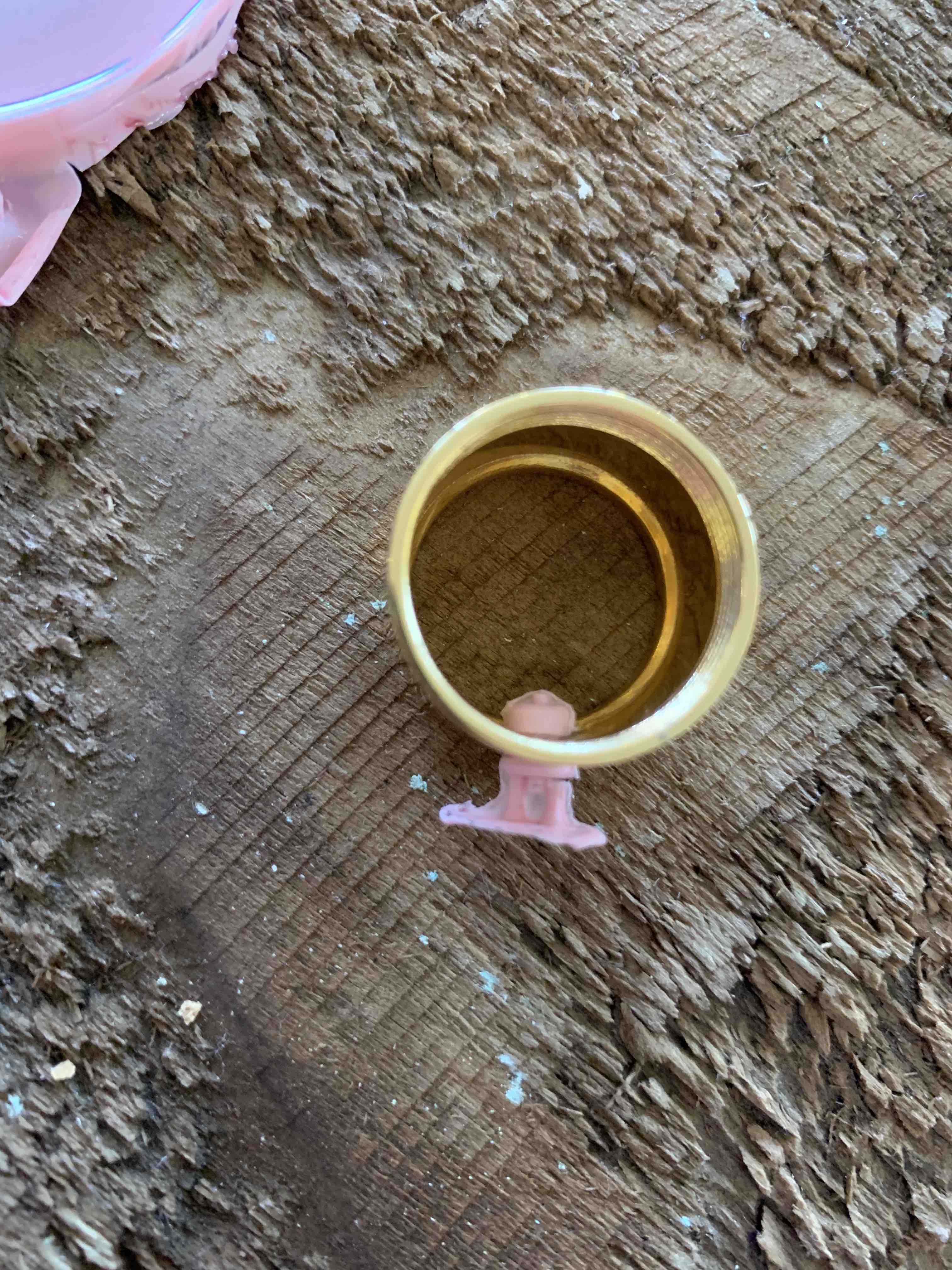
 Detail on the backing plate pickup
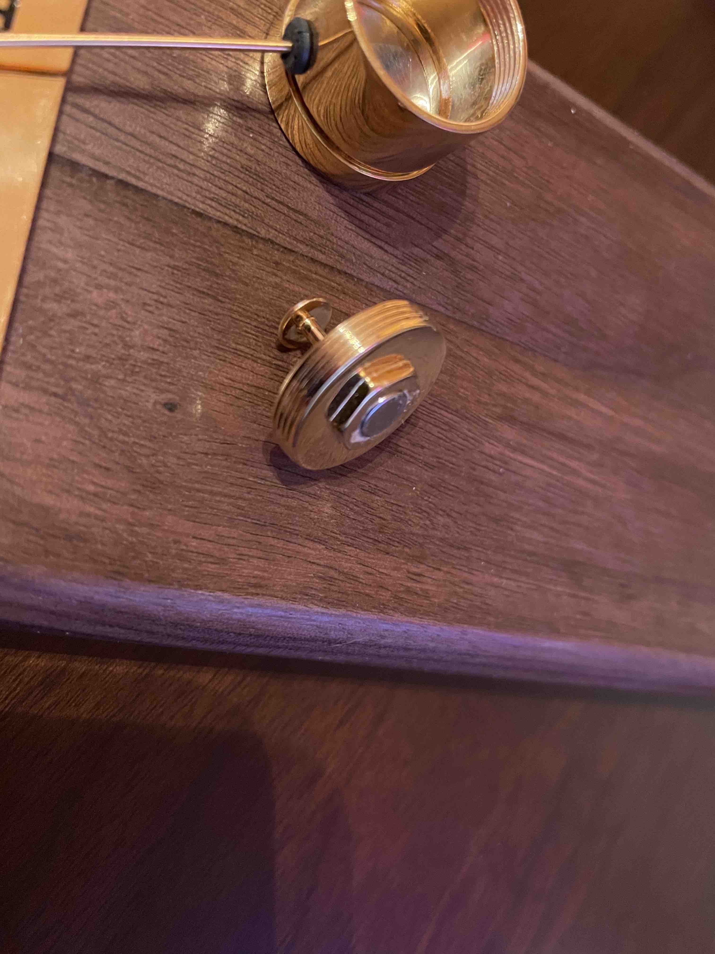 The modified backing plate with a circular inset for a magnet to attach to the plinth
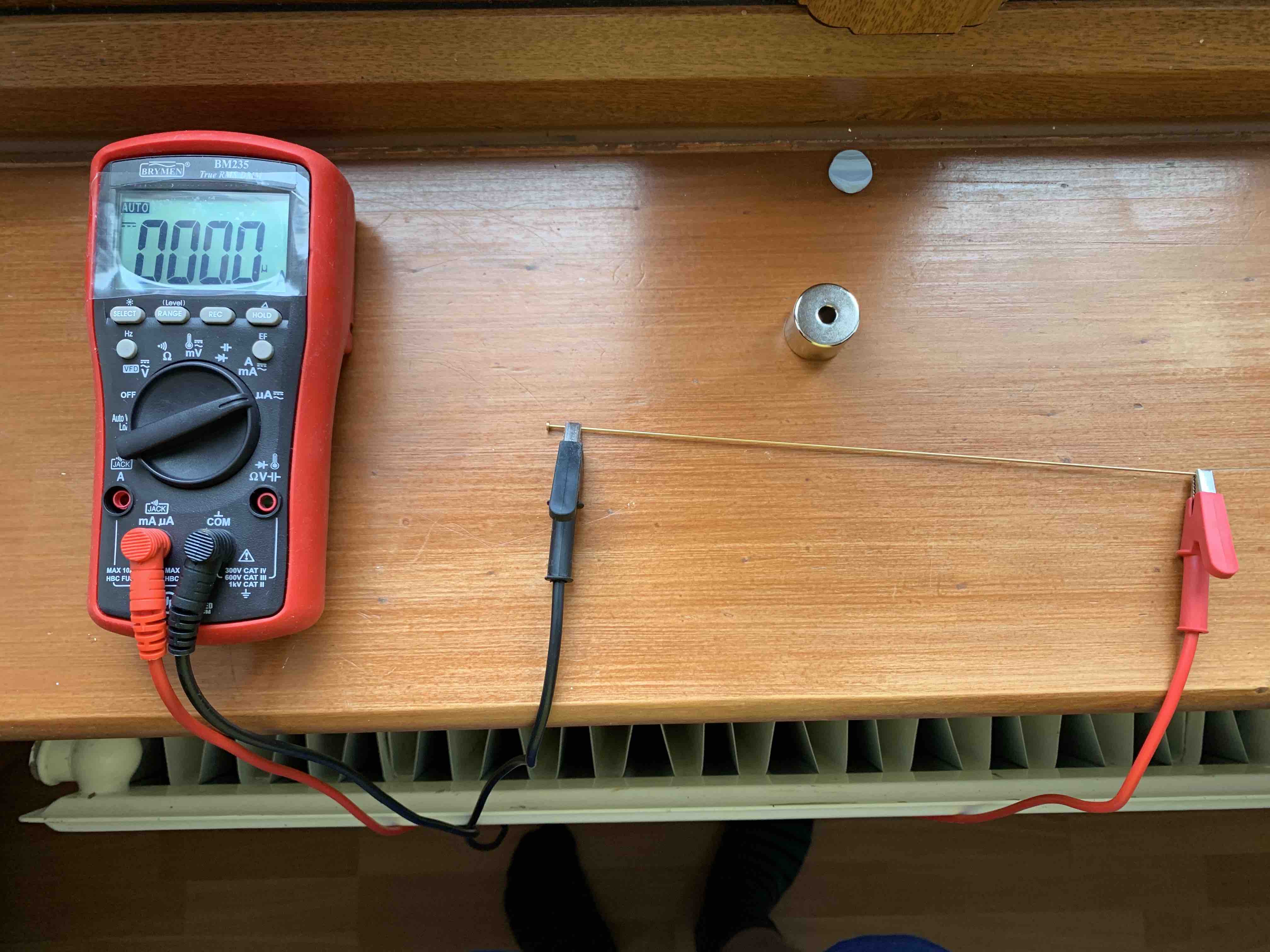 This is a model of "The Thing" it wouldn't be right not to test the antenna...
Note: Leads are in the wrong connectors.
This is a model of "The Thing" it wouldn't be right not to test the antenna...
Note: Leads are in the wrong connectors.
Throughout the build process I had to learn how to create rubber molds, Electroplate Nickel, Source different materials, Injection molding & Gold Electroplating.
It was a really fun, but long journey from inception to it hanging on my wall.
Hopefully you'll appreciate the amount of work that went into it.